In System Programming using SPI is well suited for programming devices soldered onto external target boards. This section explains how to connect the Atmel AVR Dragon to SPI program an external target. The SPI lines are equipped with level converters that automatically will level shift the AVR Dragon signals to the target board voltage.
It is recommended that a 6-pin header connector with 2.54mm (100 MIL) spacing is placed on the target board to allow easy access to the SPI programming interface. The following pinout should be used.
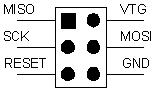
When connecting the AVR Dragon to the target, connect MISO to MISO pin on the target device, MOSI to MOSI, and so on.
AVR Dragon must sense the target voltage on pin 2 on the SPI header in order to set up the level-converters. For on-board targets, the voltage must be supplied from pin 2, 4, 6 on the VCC header (5V) into pin 2 (VTG) on the SPI header. When using off-board targets there should be no connection between the VCC header and pin 2 of the SPI header.
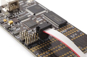
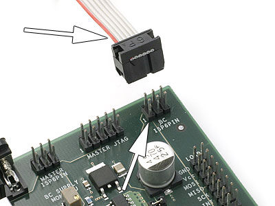
Connect the 6pin cable from the AVR Dragon to the external target as shown in these pictures:
debugWIRE OCD interface is also accessed through this SPI header.