The JTAG interface consists of a 4-wire Test Access Port (TAP) controller that is compliant with the IEEE® 1149.1 standard. The IEEE standard was developed to provide an industry-standard way to efficiently test circuit board connectivity (Boundary Scan). Atmel AVR devices have extended this functionality to include full Programming and On-Chip Debugging support.
Figure 1. Connecting the JTAG connector to
external target
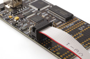
Figure 2. Connections needed to access external targets through JTAG interface
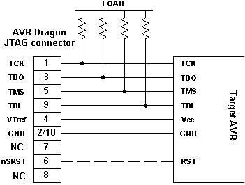
Figure 3. JTAG connector pinout
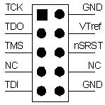
| Name | Pin | Description |
|---|---|---|
| TCK | 1 | Test Clock (clock signal from the AVR Dragon into the target device) |
| TMS | 5 | Test Mode Select (control signal from the AVR Dragon into the target device) |
| TDI | 9 | Test Data In (data transmitted from the AVR Dragon into the target device) |
| TDO | 3 | Test Data Out (data transmitted from the target device into the AVR Dragon) |
| nTRST | 8 | Test Reset (optional, only on some AVR devices). Used to reset the JTAG TAP controller. |
| nSRST | 6 | Reset (optional) Used to reset the target device. Connecting this pin is recommended since it allows the AVR Dragon to hold the target device in a reset state, which can be essential to debugging in certain scenarios. |
| VTref | 4 | Target voltage reference. The AVR Dragon samples the target voltage on this pin in order to power the level converters correctly. The AVR Dragon draws less than 1mA from this pin. |
| GND | 2, 10 | Ground. Both must be connected to ensure that the AVR Dragon and the target device share the same ground reference. |