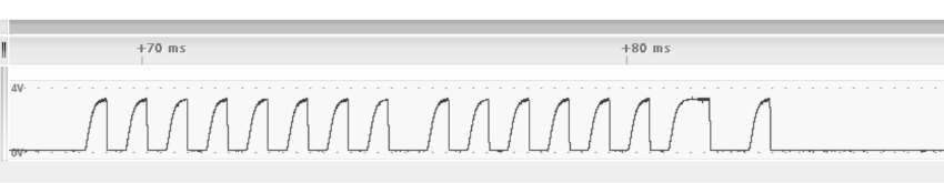
A forward frame (Start bit + 0xFE02 + Stop bits) received by the MCU is presented in the figure below:
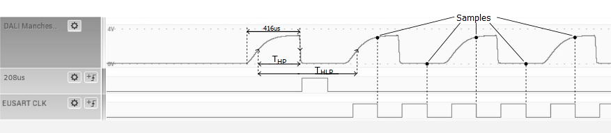
The DALI-2 bus has a data rate of 1200 bits/s. The EUSART is used to sample both halves for each bit, so its sample (baud) rate is set to 2400. The sample period, TE = 1s/2400 = 416 μs. The EUSART reading must be synchronized with the DALI-2 frame Data bits.
TMR8 is used for detecting the Start and Stop bits of the DALI frame. The timer has the Hardware Limit Timer (HLT) capability – a feature that allows the timer to be started or reset by an external event using the External Reset (TMRx_ers) pin. The mode is configured by setting the corresponding value in the T8HLTbits.MODE field. (See PIC16(L)F1777/8/9 Data Sheet for details).
Initially, the HLT mode is configured to start the timer on the falling edge of the External Reset (TMRx_ers) pin, and the timer is configured to overflow in TE/2 = 208 μs. The first falling edge occurs at the middle of the Start bit, triggering the timer, which generates the interrupt after 208 μs.
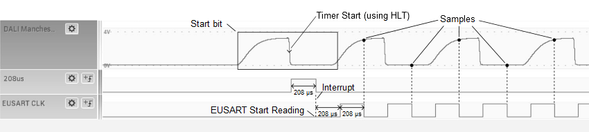
In the ISR, the EUSART continuous receive is started. The EUSART is configured as a synchronous master, with a baud rate of 2400, which is twice the data rate of the Manchester signal. In this configuration, the EUSART will sample both halves of each Manchester encoded Data bit. On the EUSART Receive ISR, the received data is stored in a buffer.
Also during the timer ISR, the timer is configured to detect the Stop condition. The HLT is configured to reset the timer for each signal edge. The timer is configured to overflow in 2.4 ms and then it is started. If there is no edge for 2.4 ms, it means that the Stop condition occurred and the end of frame was reached. The timer will generate the interrupt.
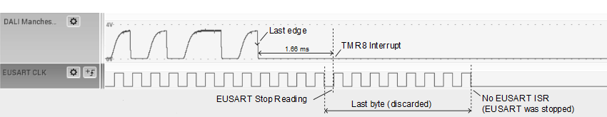
In the timer ISR, the EUSART is stopped, the timer is reconfigured for start detection, and the received data is processed. Signal error checking is performed, then the data is decoded to obtain the actual bytes and the callback function is called.
In order to correctly receive the frames, the EUSART baud rate must be equal to the baud rate of the received signal. When using the internal oscillator, the clock frequency of the PIC may drift, thus affecting the generated baud rate. An automatic baud control mechanism is implemented to compensate for that frequency drift.
It uses two timers: TMR5 for measuring the width of the first high pulse, and
TMR1 for measuring the total width of the first high + low pulses. The two measurements
are needed to get an accurate result. The measured width of the high pulse is smaller
than TE, due to the sluggish rising edge, but that difference adds up to the
end of the low pulse, so the total width will be exactly a multiple of TE.
The low pulse consists of one or two half bits, depending if the first bit (after the
Start bit) is a ‘1’, or a ‘0’.
The width of the low pulse is compared against 1.5 times the width of the high pulse, to decide whether the total (high + low) width must be divided by 2 or by 3, in order to get the actual TE. The computation is made after the frame end detection, and then the EUSART baud rate is adjusted to 1/TE for the next frame.
The TMR5 is set to count only during the first high pulse, by enabling the Gate Single-Pulse mode, with Gate Polarity high, and Gate Signal Source to the RX pin. The TMR1 is configured similarly, but also with Gate Toggle enabled, so it counts during the first high + low pulses. This automatic baud control was successfully tested for a transmitter data rate variation of -50% to +100%, with a fixed receiver clock frequency, and for a receiver clock frequency variation of -50% to +100%, with a fixed transmitter data rate (1200 bits/s).