The Atlas Scientific pH probe is connected to the Gravity pH Meter, which outputs an analog voltage range from approximately 3.0V to 0.265V (see Table 1) and can be read using the ADC of the PIC16F15245. Figure 1 is used to convert the ADC input voltage into a pH value.
| pH | Volts |
|---|---|
| 0 | 2.745 |
| 1 | 2.570 |
| 2 | 2.390 |
| 3 | 2.210 |
| 4 | 2.030 |
| 5 | 1.855 |
| 6 | 1.680 |
| 7 | 1.500 |
| 8 | 1.330 |
| 9 | 1.155 |
| 10 | 0.975 |
| 11 | 0.800 |
| 12 | 0.620 |
| 13 | 0.445 |
| 14 | 0.265 |
where:
ADC_RESULT = the ADC input conversion results, found in the ADRESH:ADRESL register pair
MAX_ADC = maximum resolution of the ADC in terms of bits
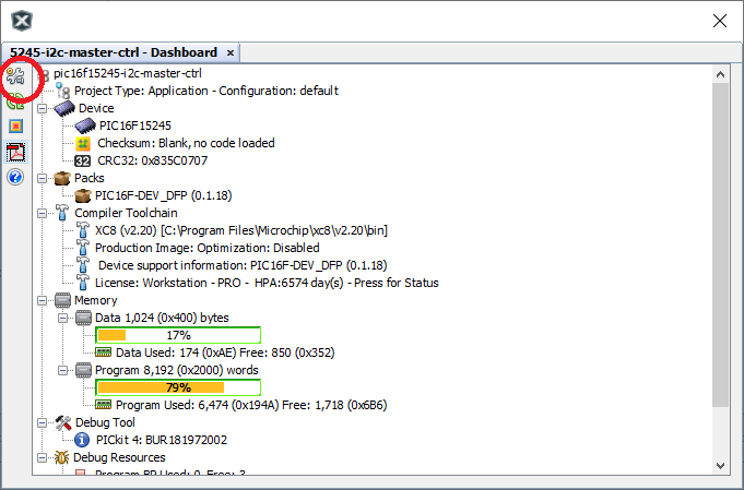
The pH calculation requires the use of floating-point arithmetic, which will require more memory. To minimize the memory requirements needed by the compiler when performing floating-point arithmetic, a small change in the MPLAB X's IDE will be required. When creating software in MPLAB X IDE version 5.40, the XC8 compiler by default uses the C99 compiler standard that utilizes 32-bit floating-point variables. For this application, 32-bit floats will not only consume more memory than is required, but also make transmitting the results over I2C much more difficult. Instead, this project will make use of the C90 standard that uses 24-bit floats.
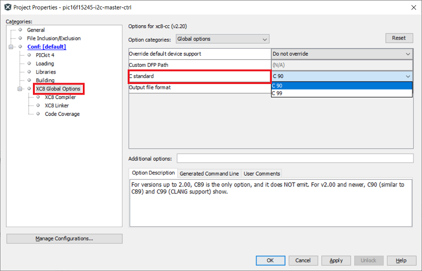
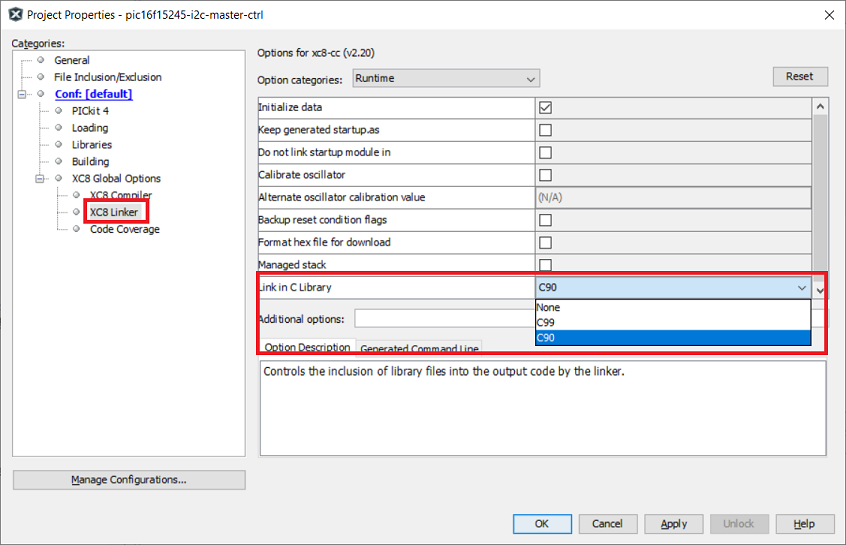
To change from the C99 to C90 standard, click on the Project Properties button (Figure 2) or File > Project Properties. In the Categories: window under XC8 Global Options, select C90 from the C standard drop down menu (see Figure 3) and click Apply. Under XC8 Linker, select C90 from the Link in C library drop down menu (see Figure 4). Click Apply.
ADC Input to pH Calculations in main() shows the lines
of code used in the project’s main while() loop. The program reads the
pH voltage provided to the analog input and converts the input into a floating-point pH
value. At this point, a printf statement outputs the pH value via the
EUSART. This is a great point to check to see if the output is what is expected.
ADC Input to pH Calculations in main()
while (1)
{
    pHSensor = ADC_GetConversion(channel_ANA2);
    pHVoltage = (pHSensor/MAX_ADC);
    pHVoltage = pHVoltage * 5;
    pHValue = (PH_SLOPE * pHVoltage);
    pHValue = pHValue + PH_OFFSET;
    printf("pH Value = %1.1f \r\n", pHValue);
}
If the system only required the pH sensor, this code snippet can read and convert the data from the probe and output the results via the EUSART. Since the system requires I2C communication, the 24-bit floating-point pH value must be converted into individual bytes that can be transmitted over the I2C bus.
Converting the 24-bit Float into Three Bytes shows the code used to convert the 24-bit float into three individual bytes that can be easily transmitted over the I2C bus. The code breaks the float into three bytes and loads them into an array. When the I2C master requests data from this slave, the slave will transmit the values contained in the array.
Converting the 24-bit Float into Three Bytes
while (1)
{
    pHSensor = ADC_GetConversion(channel_ANA2);
    pHVoltage = (pHSensor/MAX_ADC);
    pHVoltage = pHVoltage * 5;
    pHValue = (PH_SLOPE * pHVoltage);
    pHValue = pHValue + PH_OFFSET;
    (uint24_t)pHCopy = (float)pHValue * 100;

// Break down the float variable into 3 bytes
    pHLowByte = pHCopy & 0xFF;                                // Get low byte
    pHHighByte = (pHCopy >> 8) & 0xFF;                        // Get high byte
    pHUpperByte = (pHCopy >> 16) & 0xFF;                      // Get upper byte
    (uint8_t)i2cArray[0] = (uint8_t)pHLowByte;
    (uint8_t)i2cArray[1] = (uint16_t)pHHighByte;
    (uint8_t)i2cArray[2] = (uint24_t)pHUpperByte;
}
Before the data is transmitted, the math used to convert the float into three integer bytes should be checked. This is accomplished by using the same method the master would use to convert the three integers back into the 24-bit float. Converting Three Bytes into a 24-bit Float adds the extra code that the master will use to convert the three integers back into a floating-point variable. Again, the data is sent over the EUSART so that the results can be easily verified.
Converting Three Bytes into a 24-bit Float
while (1)
{
    pHSensor = ADC_GetConversion(channel_ANA2);
    pHVoltage = (pHSensor/MAX_ADC);
    pHVoltage = pHVoltage * 5;
    pHValue = (PH_SLOPE * pHVoltage);
    pHValue = pHValue + PH_OFFSET;
    (uint24_t)pHCopy = (float)pHValue * 100;

// Break down the float variable into 3 bytes to transmit
    pHLowByte = pHCopy & 0xFF;                                // Get low byte
    pHHighByte = (pHCopy >> 8) & 0xFF;                        // Get high byte
    pHUpperByte = (pHCopy >> 16) & 0xFF;                      // Get upper byte
    (uint8_t)i2cArray[0] = (uint8_t)pHLowByte;
    (uint8_t)i2cArray[1] = (uint16_t)pHHighByte;
    (uint8_t)i2cArray[2] = (uint24_t)pHUpperByte;
// Test convert back into 24-bit float
    (uint24_t)newpH = ((uint24_t)i2cArray[2] << 16);
    (uint24_t)newpH = (uint24_t)newpH + ((uint16_t)i2cArray[1] << 8);
    (uint24_t)newpH = (uint24_t)newpH + i2cArray[0];

    (float)pHValue = (uint24_t)newpH;
    pHValue /= 100.00;
    printf("pH Value = %1.1f \r\n", pHValue);
}
Once the results are verified, the last step is to add the I2C slave drivers. I2C Configuration and Interrupt Service Routine shows the MSSP configuration and Interrupt Service Routine. The MSSP is configured in I2C Slave mode and uses the Interrupt Service Routine to transmit data to the master upon request.
I2C Configuration and Interrupt Service Routine
void I2C_Initialize(void)
{
    SSP1STATbits.SMP = 1;                // Disable slew control
    SSP1CON1bits.SSPM = 0b0110;          // 7-bit slave mode
    SSP1CON2bits.SEN = 1;                // Enable clock stretching
    SSP1CON3bits.SBCDE = 1;              // Enable bus collision interrupts
    SSP1ADD = slaveAddress;              // Load slave address
    SSP1CON1bits.SSPEN = 1;              // Enable the module

    PIR1bits.BCL1IF = 0;                 // Clear Bus Collision interrupt flag
    PIR1bits.SSP1IF = 0;                 // Clear the SSP interrupt flag
    PIE1bits.BCL1IE = 1;                 // Enable BCLIF
    PIE1bits.SSP1IE = 1;                 // Enable SSPIF
    INTCONbits.PEIE = 1;                 // Enable peripheral interrupts
    INTCONbits.GIE = 1;                  // Enable global interrupts
}

void __interrupt() ISR(void)
{
    if(PIR1bits.SSP1IF)                  // Check for SSPIF
    {
        if(SSP1STATbits.R_nW == 1)       // Master to read (slave transmit)
        {
            SSP1BUF = i2cArray[index++]; // Load array value
            SSP1CON1bits.CKP = 1;        // Release clock stretch
        }
        if(SSP1STATbits.R_nW == 0)       // Master to write (slave receive)
        {
            if(SSP1STATbits.D_nA == 0)   // Last byte was an address
            {
                regAdd = 1;              // Next byte will be register address
                temp = SSP1BUF;          // Clear BF
                SSP1CON1bits.CKP = 1;    // Release clock stretch
            }
            if(SSP1STATbits.D_nA == 1)   // Last byte was data
            {
                if(regAdd == 1)          // Last byte was the register address
                {
                    index = SSP1BUF;     // Load register address into index
                    regAdd = 0;          // Next byte will be true data
                }
                else
                {
                    if(index < ARRAY_CNT)     // Within array boundaries?
                    {
                        i2cArray[index++] = SSP1BUF;  // Yes, load data
                    }
                    else
                    {
                        temp = SSP1BUF;      // No, loc invalid, discard data
                    }
                }
                SSP1CON1bits.CKP = 1;        // Release clock stretch
            }
        }
    }
    if(PIR1bits.BCL1IF == 1)
    {
        temp = SSP1BUF;                     // Clear BF
        PIR1bits.BCL1IF = 0;                // Clear BCLIF
        SSP1CON1bits.CKP = 1;               // Release clock stretching
    }
    PIR1bits.SSP1IF = 0;                    // Clear SSP1IF
}