The MSS DDR subsystem consists of the following hard blocks:
- DDR controller
- Training logic
- I/O lane
- Phase-Locked Loop (PLL)
The following figure shows the memory interface solution that can be created using the MSS DDR controller.
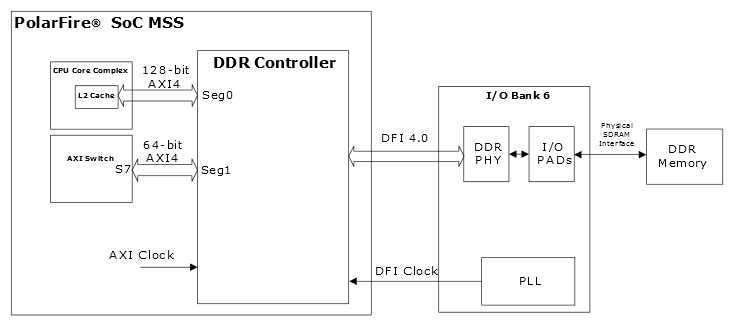
The following points summarize the data flow:
- 1.The E51 monitor core initializes the DDR controller.
- 2.The DDR subsystem accepts read and write commands from the following masters:
- CPU Core Complex: Processor cores can access the DDR controller using the 128-bit AXI4 interface via the Seg0 segmentation block.
- Fabric Master: Fabric masters can access the DDR controller using the 64-bit AXI4 interface via the Seg1 segmentation block through the S7 slave port of the AXI Switch.
For more information about the CPU Core Complex and the AXI Switch memory map, see PolarFire SoC Device Register Map.
- 3.
The MSS DDR controller issues these commands to the DDR PHY, which sends and receives data to/from the DDR SDRAM via the MSS DDR BANK 6 I/Os.
The MSS DDR subsystem is configured using the standalone MSS Configurator. The standalone MSS Configurator includes the required DDR configuration tabs that enable manual configuration of topology, memory initialization, and timing parameters. For more information about configuring the MSS DDR subsystem, see Standalone MSS Configurator User Guide for PolarFire SoC .