Each processor core supports Local and Global Interrupts. 48 interrupts from peripherals are directly connected as Local interrupts to each processor core. Local interrupts are handled faster than the Global interrupts. The Core Local Interrupt Controller (CLINT) block generates Software and Timer Interrupts which are also Local interrupts.
- Enable the required Global interrupts
- Route the interrupt to a specific core
- Assign priority to those interrupts
- Assign priority threshold levels
Some application critical Global interrupts can also be routed as Local interrupts. All interrupts are synchronized with the AXI/CPU clock domain for relaxed timing requirements. For a Hart, the latency of Global interrupts increases with the ratio of the core clock frequency to the clock frequency.
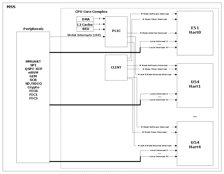
Table 1 lists the Local and Global interrupts implemented in the MSS.
- The spi0 interrupt signal is a Global interrupt because it is not connected to any Hart as a Local interrupt. This interrupt signal is connected to the PLIC.
- The mac0_int interrupt signal is a Local interrupt to Hart1 and Hart2. It can also be enabled as a Global interrupt via the PLIC to Hart0, Hart3, and Hart4.
| Interrupt | Width | Global_int | IRQ | Hart0 | Hart1 | Hart2 | Hart3 | Hart4 | M2F-Vect | M2F-Int | U54-Mask |
|---|---|---|---|---|---|---|---|---|---|---|---|
| MSS_INT_F2M[63:32] | 32 | [168:137] | [181:150] | [47:16] | — | — | — | — | — | — | — |
| MSS_INT_F2M[31:0] | 32 | [136:105] | [149:118] | — | [47:16] | [47:16] | [47:16] | [47:16] | — | — | MASKED |
| gpio0/2 | 14 | [13:0] | [26:13] | — | — | — | — | — | [13:0] | 0 | — |
| gpio1/2 | 24 | [37:14] | [50:27] | — | — | — | — | — | [37:14] | 0 | — |
| gpio0_non_direct | 1 | 38 | 51 | — | — | — | — | — | 38 | 0 | — |
| gpio1_non_direct | 1 | 39 | 52 | — | — | — | — | — | 39 | 0 | — |
| gpio2_non_direct | 1 | 40 | 53 | — | — | — | — | — | 40 | 0 | — |
| spi0 | 1 | 41 | 54 | — | — | — | — | — | 41 | 1 | — |
| spi1 | 1 | 42 | 55 | — | — | — | — | — | 42 | 1 | — |
| can0 | 1 | 43 | 56 | — | — | — | — | — | 43 | 1 | — |
| can1 | 1 | 44 | 57 | — | — | — | — | — | 44 | 1 | — |
| i2c0_main | 1 | 45 | 58 | — | — | — | — | — | 45 | 2 | — |
| i2c0_alert | 1 | 46 | 59 | — | — | — | — | — | 46 | 2 | — |
| i2c0_sus | 1 | 47 | 60 | — | — | — | — | — | 47 | 2 | — |
| i2c1_main | 1 | 48 | 61 | — | — | — | — | — | 48 | 2 | — |
| i2c1_alert | 1 | 49 | 62 | — | — | — | — | — | 49 | 2 | — |
| i2c1_sus | 1 | 50 | 63 | — | — | — | — | — | 50 | 2 | — |
| mac0_int | 1 | 51 | 64 | — | 8 | 8 | — | — | 51 | 3 | MASKED |
| mac0_queue1 | 1 | 52 | 65 | — | 7 | 7 | — | — | 52 | 3 | MASKED |
| mac0_queue2 | 1 | 53 | 66 | — | 6 | 6 | — | — | 53 | 3 | MASKED |
| mac0_queue3 | 1 | 54 | 67 | — | 5 | 5 | — | — | 54 | 3 | MASKED |
| mac0_emac | 1 | 55 | 68 | — | 4 | 4 | — | — | 55 | 3 | MASKED |
| mac0_mmsl | 1 | 56 | 69 | — | 3 | 3 | — | — | 56 | 3 | MASKED |
| mac1_int | 1 | 57 | 70 | — | — | — | 8 | 8 | 57 | 4 | MASKED |
| mac1_queue1 | 1 | 58 | 71 | — | — | — | 7 | 7 | 58 | 4 | MASKED |
| mac1_queue2 | 1 | 59 | 72 | — | — | — | 6 | 6 | 59 | 4 | MASKED |
| mac1_queue3 | 1 | 60 | 73 | — | — | — | 5 | 5 | 60 | 4 | MASKED |
| mac1_emac | 1 | 61 | 74 | — | — | — | 4 | 4 | 61 | 4 | MASKED |
| mac1_mmsl | 1 | 62 | 75 | — | — | — | 3 | 3 | 62 | 4 | MASKED |
| ddrc_train | 1 | 63 | 76 | — | — | — | — | — | 63 | 9 | — |
| scb_interrupt | 1 | 64 | 77 | 15 | — | — | — | — | 64 | 7 | — |
| peripheral_ecc_error1 | 1 | 65 | 78 | 14 | — | — | — | — | 65 | 6 | — |
| peripheral_ecc_correct1 | 1 | 66 | 79 | 13 | — | — | — | — | 66 | 6 | — |
| rtc_wakeup | 1 | 67 | 80 | — | — | — | — | — | 67 | 11 | — |
| rtc_match | 1 | 68 | 81 | — | — | — | — | — | 68 | 11 | — |
| timer1 | 1 | 69 | 82 | — | — | — | — | — | 69 | 12 | — |
| timer2 | 1 | 70 | 83 | — | — | — | — | — | 70 | 12 | — |
| envm | 1 | 71 | 84 | 12 | — | — | — | — | 71 | 13 | — |
| qspi | 1 | 72 | 85 | — | — | — | — | — | 72 | 13 | — |
| usb_dma | 1 | 73 | 86 | — | — | — | — | — | 73 | 14 | — |
| usb_mc | 1 | 74 | 87 | — | — | — | — | — | 74 | 14 | — |
| mmc_main | 1 | 75 | 88 | — | — | — | — | — | 75 | 15 | — |
| mmc_wakeup | 1 | 76 | 89 | — | — | — | — | — | 76 | 15 | — |
| mmuart0 | 1 | 77 | 90 | 11 | — | — | — | — | 77 | 1 | — |
| mmuart1 | 1 | 78 | 91 | — | 11 | — | — | — | 78 | 1 | — |
| mmuart2 | 1 | 79 | 92 | — | — | 11 | — | — | 79 | 1 | — |
| mmuart3 | 1 | 80 | 93 | — | — | — | 11 | — | 80 | 1 | — |
| mmuart4 | 1 | 81 | 94 | — | — | — | — | 11 | 81 | 1 | — |
| wdog0_mvrp | 1 | 87 | 100 | 10 | — | — | — | — | 87 | 5 | — |
| wdog1_mvrp | 1 | 88 | 101 | — | 10 | — | — | — | 88 | 5 | — |
| wdog2_mvrp | 1 | 89 | 102 | — | — | 10 | — | — | 89 | 5 | — |
| wdog3_mvrp | 1 | 90 | 103 | — | — | — | 10 | — | 90 | 5 | — |
| wdog4_mvrp | 1 | 91 | 104 | — | — | — | — | 10 | 91 | 5 | — |
| wdog0_tout | 1 | 92 | 105 | 9 | — | — | — | — | 92 | 5 | — |
| wdog1_tout | 1 | 93 | 106 | 8 | 9 | — | — | — | 93 | 5 | — |
| wdog2_tout | 1 | 94 | 107 | 7 | — | 9 | — | — | 94 | 5 | — |
| wdog3_tout | 1 | 95 | 108 | 6 | — | — | 9 | — | 95 | 5 | — |
| wdog4_tout | 1 | 96 | 109 | 5 | — | — | — | 9 | 96 | 5 | — |
| g5c_devrst | 1 | 82 | 95 | 4 | — | — | — | — | 82 | 10 | — |
| g5c_message | 1 | 83 | 96 | 3 | — | — | — | — | 83 | 8 | — |
| usoc_vc_interrupt | 1 | 84 | 97 | 2 | — | — | — | — | 84 | 11 | — |
| usoc_smb_interrupt | 1 | 85 | 98 | 1 | — | — | — | — | 85 | 11 | — |
| pll_event | 1 | 86 | 99 | 0 | — | — | — | — | 86 | 6 | — |
| mpu_fail | 1 | 86 | 99 | 0 | — | — | — | — | 86 | 6 | — |
| decode_error | 1 | 86 | 99 | 0 | — | — | — | — | 86 | 6 | — |
| lp_state_enter | 1 | 86 | 99 | 0 | — | — | — | — | 86 | 6 | — |
| lp_state_exit | 1 | 86 | 99 | 0 | — | — | — | — | 86 | 6 | — |
| ff_start | 1 | 86 | 99 | 0 | — | — | — | — | 86 | 6 | — |
| ff_end | 1 | 86 | 99 | 0 | — | — | — | — | 86 | 6 | — |
| fpga_on | 1 | 86 | 99 | 0 | — | — | — | — | 86 | 6 | — |
| fpga_off | 1 | 86 | 99 | 0 | — | — | — | — | 86 | 6 | — |
| scb_error | 1 | 86 | 99 | 0 | — | — | — | — | 86 | 6 | — |
| scb_fault | 1 | 86 | 99 | 0 | — | — | — | — | 86 | 6 | — |
| mesh_fail | 1 | 86 | 99 | 0 | — | — | — | — | 86 | 6 | — |
| io_bank_b2_on | 1 | 86 | 99 | 0 | — | — | — | — | 86 | 6 | — |
| io_bank_b4_on | 1 | 86 | 99 | 0 | — | — | — | — | 86 | 6 | — |
| io_bank_b5_on | 1 | 86 | 99 | 0 | — | — | — | — | 86 | 6 | — |
| io_bank_b6_on | 1 | 86 | 99 | 0 | — | — | — | — | 86 | 6 | — |
| io_bank_b2_off | 1 | 86 | 99 | 0 | — | — | — | — | 86 | 6 | — |
| io_bank_b4_off | 1 | 86 | 99 | 0 | — | — | — | — | 86 | 6 | — |
| io_bank_b5_off | 1 | 86 | 99 | 0 | — | — | — | — | 86 | 6 | — |
| io_bank_b6_off | 1 | 86 | 99 | 0 | — | — | — | — | 86 | 6 | — |
| g5c_mss_spi | 1 | 97 | 110 | — | — | — | — | — | 97 | 13 | — |
| volt_temp_alarm | 1 | 98 | 111 | — | — | — | — | — | 98 | No | — |
| athena_complete | 1 | 99 | 112 | — | — | — | — | — | NA | No | — |
| athena_alarm | 1 | 100 | 113 | — | — | — | — | — | NA | No | — |
| athena_buserror | 1 | 101 | 114 | — | — | — | — | — | NA | No | — |
| usoc_axic_us | 1 | 102 | 115 | — | — | — | — | — | 102 | 11 | — |
| usoc_axic_ds | 1 | 103 | 116 | — | — | — | — | — | 103 | 11 | — |
| reserved/spare | 11 | [104] | [117] | 0 | 7 | 7 | 7 | 7 | NA | — | — |
|
Note:
|
To enable all Local interrupts on the U54_1 core, set the FAB_INTEN_U54_1 register using the SYSREG->FAB_INTEN_U54_1 = 0xffffffff;instruction. This instruction enables all MSS_INT_F2M[31:0] interrupts to interrupt U54_1 directly. Similarly, enable the Local interrupts on U54_2, U54_3, and U54_4 cores.
By default, all Local interrupts MSS_INT_F2M[63:32] are enabled on the E51 core.