The Advanced DMA Mode Version 2 (ADMA2) uses the Descriptors List to describe data transfers. The SD Host registers only define the base address of the Descriptors List. The base addresses and sizes of the data pages are defined inside the descriptors. The SD Host supports ADMA2 in 64-bit or 32-bit Addressing mode.
When in ADMA2 mode, the SD Host transfers data from the data pages. Page is a block of valid data that is defined by a single ADMA2 descriptor. Each ADMA2 descriptor can define only one data page. The starting address of the data page must be aligned to the 4 byte boundary (the 2 LSbs set to 0) in 32-bit Addressing mode, and to the 8 byte boundary (the 3 LSbs are set to 0) in 64-bit Addressing mode. The size of each data page is arbitrary and it depends on neither the previous nor the successive page size. It can also be different from the SD card transfer block size (SRS01.TBS).
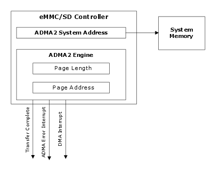
The ADMA2 engine transfers are configured in a Descriptor List. The base address of the list is set in the ADMA System Address register (SRS22.DMASA1, SRS23.DMASA2), regardless of whether it is a read or write transfer. The ADMA2 Descriptor List consists of a number of 64-bit / 96-bit / 128-bit descriptors of different functions. Each descriptor can:
- Perform transfer of a data page of specified size
- Link next descriptor address to an arbitrary memory location
| Bit | Symbol | Description |
|---|---|---|
| [95:32]/[63:32] | ADDRESS | The field contains data page address or next Descriptor List address depending on the descriptor type. When the descriptor is type TRAN, the field contains the page address. When the descriptor type is LINK, the field contains address for the next Descriptor List. |
| [31:16] | LENGTH | The field contains data page length in bytes. If this field is 0, the page length is 64 Kbytes. |
| [5:4] | ACT | The field defines the type of the
descriptor. 2’b00 (NOP) – no operation, go to next descriptor on the list 2’b01 (Reserved) – behavior identical to NOP 2’b10 (TRAN) – transfer data from the pointed page and go to the next descriptor on the list 2’b11 (LINK) – go to the next Descriptor List pointed by ADDRESS field of this descriptor. |
| 2 | INT | When this bit is set, the DMA Interrupt (SRS12.DMAINT) is generated when the ADMA2 engine completes processing of the descriptor. |
| 1 | END | When this bit is set, it signals termination of the transfer and generates Transfer Complete Interrupt when this transfer is completed. |
| 0 | VAL | When this bit is set, it indicates the
valid descriptor on a list. When this bit is cleared, the ADMA Error Interrupt is generated and the ADMA2 engine stops processing the Descriptor List. This bit prevents ADMA2 engine runaway due to improper descriptors. |