The SPI controller supports Master and Slave modes of an operation.
- In Master mode, the SPI generates SPI_X_CLK, selects a slave using SPI_X_SS, transmits the data on SPI_X_DO, and receives the data on SPI_X_DI.
- In Slave mode, the SPI is selected by SPI_X_SS. The SPI receives a clock on SPI_X_CLK and incoming data on SPI_X_DI.
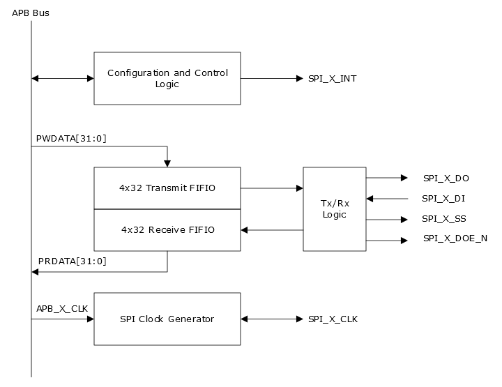
The SPI peripherals consist mainly of the following components (see Figure 1).
- Transmit and receive FIFOs
- Configuration and control logic
- SPI clock generator
The following figure shows the SPI controller block diagram.
Figure 1. SPI Controller Block
Diagram
Notes:
-
The SPI_X_DO, SPI_X_DI, SPI_X_SS, and SPI_X_CLK signals are available to the FPGA fabric.
- SPI_X_DOE_N is accessible through the SPI control register.
- SPI_X_INT is sent to the MSS Core Complex.
Note: X is used as a place holder for 0 or 1 in the register
and signal descriptions. It indicates SPI _0 (on the APB_0 bus) or SPI_1 (on the APB_1
bus).