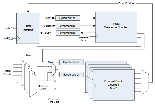
Figure 1 shows the block diagram of FRQ meter. To measure the frequency, a known clock is applied as a reference clock input. The input clock to be measured is applied to the channel counters. The FSM resets all the counters and enables the channel counters for a predefined duration generated from the reference counter. Now, the clock frequency can be calculated by reading the channel counters. For example, the reference counter is set to 10,000 and reference frequency is 50 MHz, if the channel counters return 20,000, the measured clock is 100 MHz.
To measure time, a known clock is applied to the reference clock input, this is multiplexed to the channel counters. The FSM resets all the counters and then enables the channel counters. When the external “enable” signal is active, the channel counter increments and stops all the channel counters. The time can be calculated by reading the channel counters. For example, the reference frequency is 50 MHz, if the channel counter returns 20,000, the measured time is 400,000 ns.