The ATSAMR30M Sensor Board supports the Standalone mode with an external programmer/debugger (Atmel-ICE or SAM-ICE™) and a UART-USB converter (like FTDI Cable) interfaced to UART pins of J2 for evaluation. To supply power, connect the board with either a 3V coin cell battery or a 3.3V through J5 header (external supply).
The setup shown in the following figure consists of a jumper configuration for the LDO Selection mode. To power the module across the operating voltage range of 1.8V to 3.63V, the jumpers must be in LDO Bypass mode.
Note: Refer to Section LDO Selection/Bypass Header for more
details.
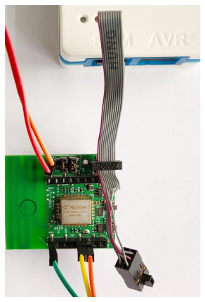
Figure 1. Sensor Board Setup with External
Programmer/Debugger, UART-USB Converter and External Supply