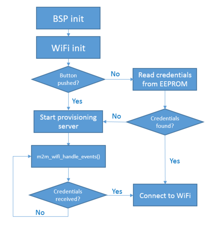
When running the application for the first time, the ATWINC1500 needs to be connected to a wireless network. To provide the SSID and password of the available Wi-Fi to the ATWINC1500, it must be placed in provisioning mode. This is done by holding down the push-button on the board when powering it up. When the LED on the I/O1 Xplained is lit, the button can be let go. Now that the ATWINC1500 is placed in provisioning mode, it will create its own access point called AVR_for_IoT.
Provisioning mode is built-in functionality of the ATWINC1500, and can be started with a function call in software. In this mode, the ATWINC1500 acts as an access point with the sole purpose of displaying a web page, which can be used to type in the credentials to a network. The application will get a callback when the ATWINC1500 has received the credentials, and this can then be used to connect to the network.
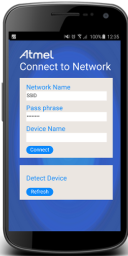
Type in the SSID and password of the network and press the "Connect" button, which will send the credentials to the ATWINC1500. Note that the Device Name field is unused. The ATWINC1500 firmware will disable the access point and send the information about the SSID and password to the application. As the access point is disabled, the phone or computer will be disconnected from the Wi-Fi, and an error message might be shown in the browser. When the credentials is received in the application, the LED will be turned off. The application will then try to connect to the provided Wi-Fi network.
When the Wi-Fi credentials have been received, the MCU will store it in EEPROM, so that it is not necessary to repeat the provisioning process each time the MCU is powered on. If the push-button on the Xplained Mini is not pressed during power on, the SSID and password will be read from EEPROM if present, and the application will try to connect with these credentials directly.
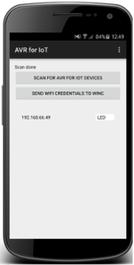
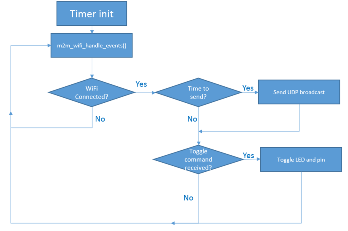
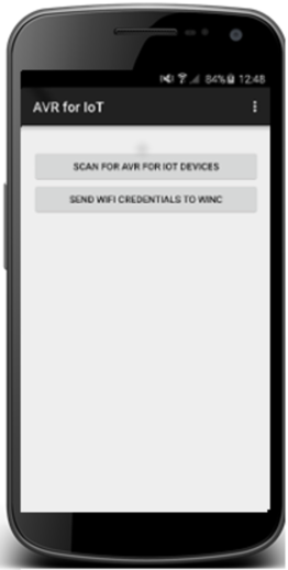
When the application is connected to the access point and has gotten an IP address, it will configure a timer and use this to broadcast UDP packets every four seconds. As these packets are broadcasted on the network, any Android phone or computer connected to the same access point will receive these packets. To let the Android application listen for UDP packets from the Xplained Mini, press the "SCAN" button.
This will initiate a scan on the network for approximately six seconds, and then show any nearby Xplained Mini with ATWINC1500 devices connected to the same wireless network as the Android phone. The IP address of any available device is shown, and when this is pressed, the LED on the I/O1 Xplained will toggle.
The pin header on the top left side of the Xplained Mini board will also toggle, allowing the demo to be connected to anything external that can be controlled by a pin.