Two extension headers needs to be soldered to the Xplained Mini board. This should be 10ˣ2 angled 100 mil headers, and they must be soldered to the bottom of the board. The optional single pin header should be soldered to the top of the board.
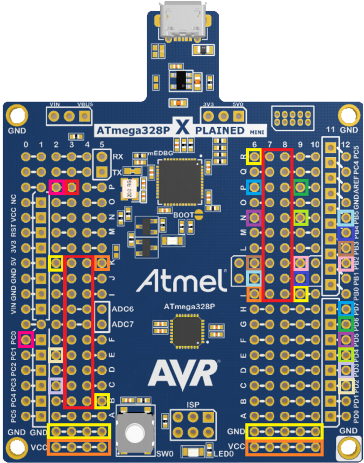
In the figure below, the connections that need to be made are color coded.
The red markings show where the headers should be placed. The connections should be made
from the hole next to the pin header to the hole marked with the corresponding color on
the sides of the board. There are several connections to GND and VCC, marked with yellow
and orange. These connections should go from the hole next to the pin headers to any of
the GND and VCC holes marked at the bottom of the board.
Figure 1. Xplained Mini Board with
Connections
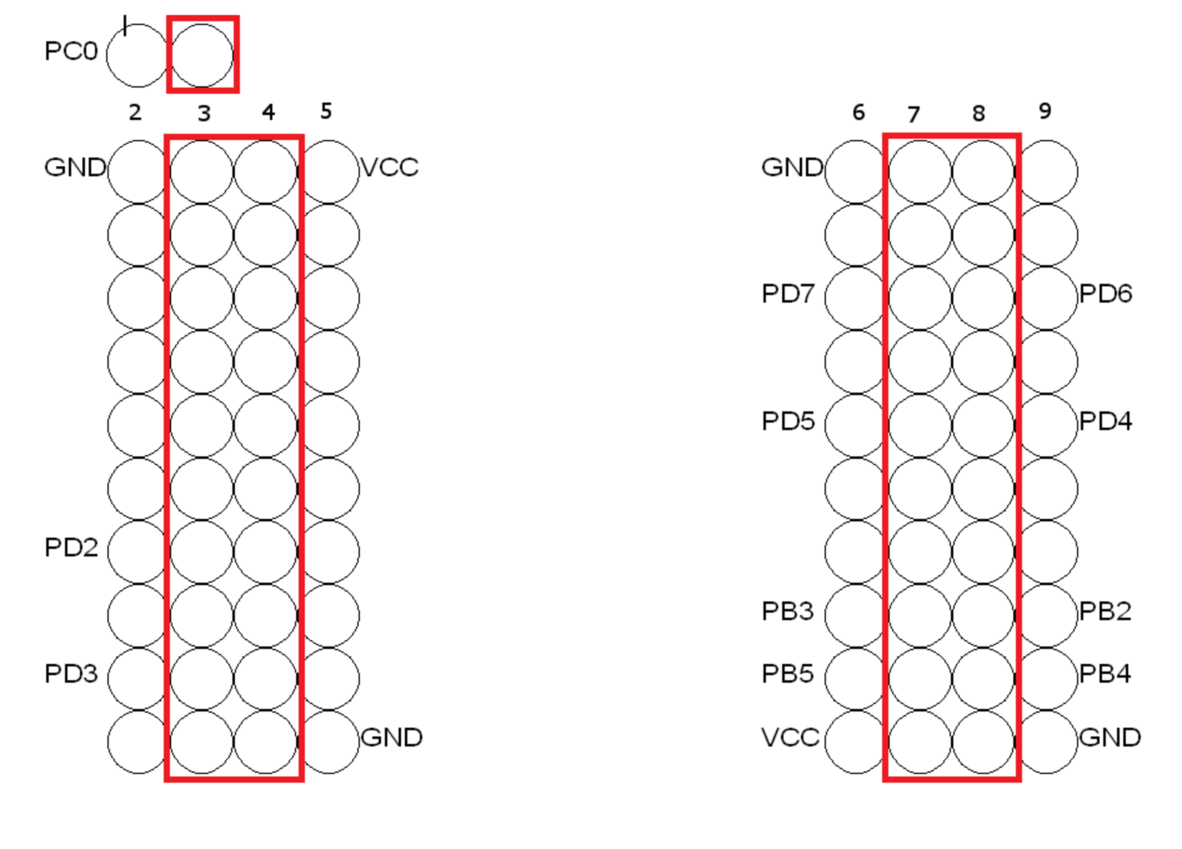
In the following figure, which pin that should be wired to which pin header is marked with the name of the pin. Note that even though the extension headers should be soldered to the bottom of the board, the drawings are from the top. To make the soldering process easier, it is recommended to solder the wires to the top of the board and to solder the wires before the extension headers.
Figure 2. Pin Connections