The timer can be configured to be clocked from an external aperiodic source
as per the settings shown in Table 2-11.
| Timer Setting | Value |
|---|---|
| START | None (ON = 1) |
| RESET | None |
| STOP | At PR Match |
| CSYNC (Clock Sync) | Async |
| CLK (Timer Clock) | External Input |
| RDSEL (Read Select) | TUxyTMR Access |
With the external input being used as the clock, the counter will advance with each clock
after the timer is enabled (ON = 1). The rest of the timer module will
operate the way it is configured – this includes ERS input, Stop, Reset, PR match,
interrupts, etc.
Reading from the TUxyCR capture register is not desirable in this use case
because the capture event requires at least one timer clock to happen, which is not
ensured in an aperiodic operation. Hence, the user can read the TUxyTMR counter register
directly with RDSEL = 1, keeping in mind that the TUxyTMR register is
not buffered and is not guarded against clock collisions when read by software.
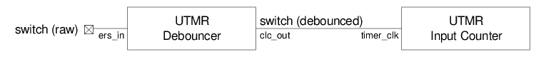
The clock input may be filtered using a separate debouncer, as shown in
Figure 2-16.
Figure 1. Input Counter
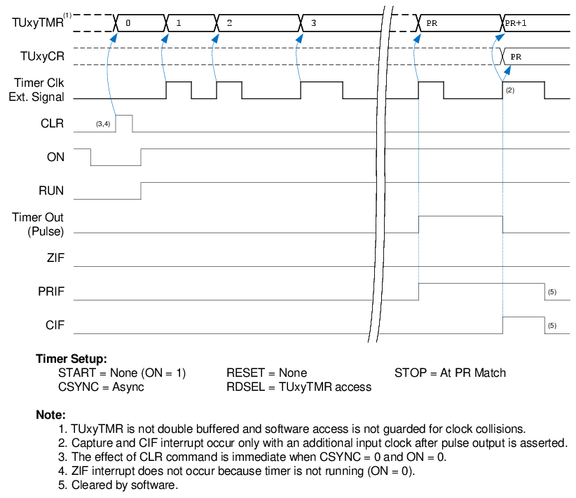
Figure 2. Cascading Input Counter with
Debouncer