The timer can be configured to be used as a hardware-based switch debouncer
as per the settings shown in Table 2-10.
| Timer Setting | Value |
|---|---|
| START | Either ERS Edge |
| RESET | At Start + PR Match |
| STOP | PR Match |
| CSYNC (Clock Sync) | Sync |
| EPOL (ERS Polarity) |
True Level (to trigger to rising edge) Inverted Level (to trigger to falling edge) |
| PR (Period Register) | Desired minimum pulse width |
Initialize the timer counter by setting the CLR command. When the input rises (changes from 0 to 1), the counter will begin counting. Any more input changes will be ignored unless a rising edge occurs near the PR match, which will override the Stop condition, reset the counter, and continue counting. This is shown in Figure 2-13.
With any input change, the counter is reset and begins counting. When the
counter reaches PR, the output changes and causes an interrupt. This is shown in Figure 2-13 below. The
interrupt software, knowing that the input is stable, can read the raw switch input to
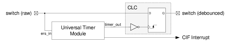
determine if the switch is open or closed. Alternatively, the D flip-flop in a CLC may
be used to sample the input, as illustrated below in Figure 2-14.
Figure 1. Switch Debouncer
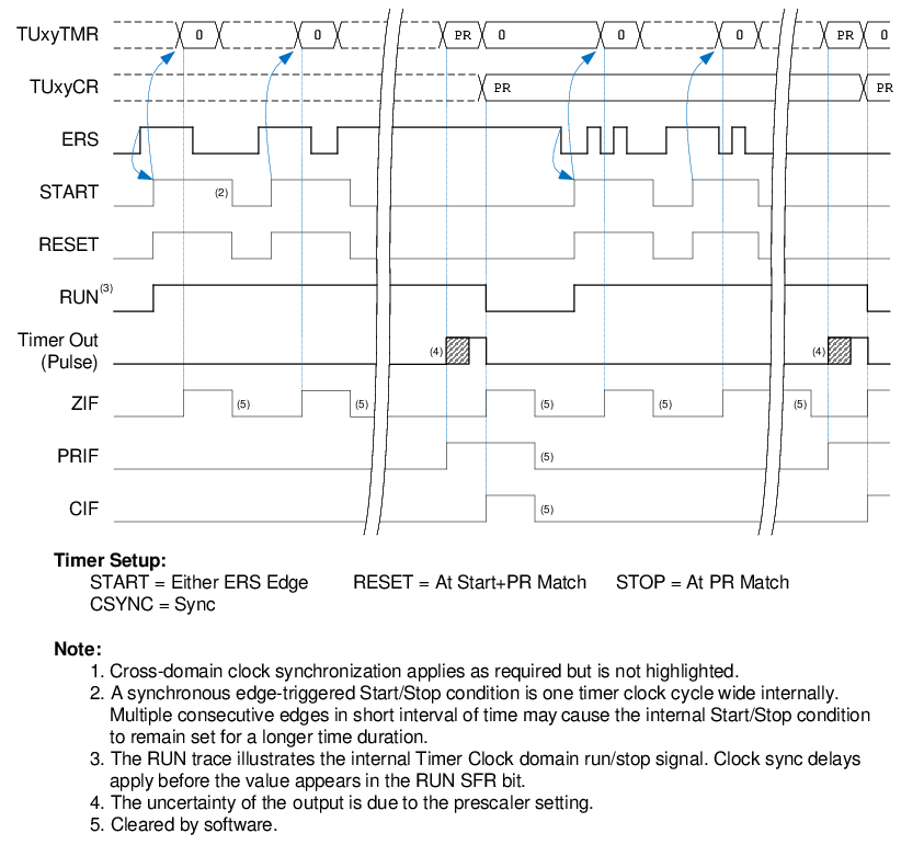
Figure 2. UTMR and CLC
Connection