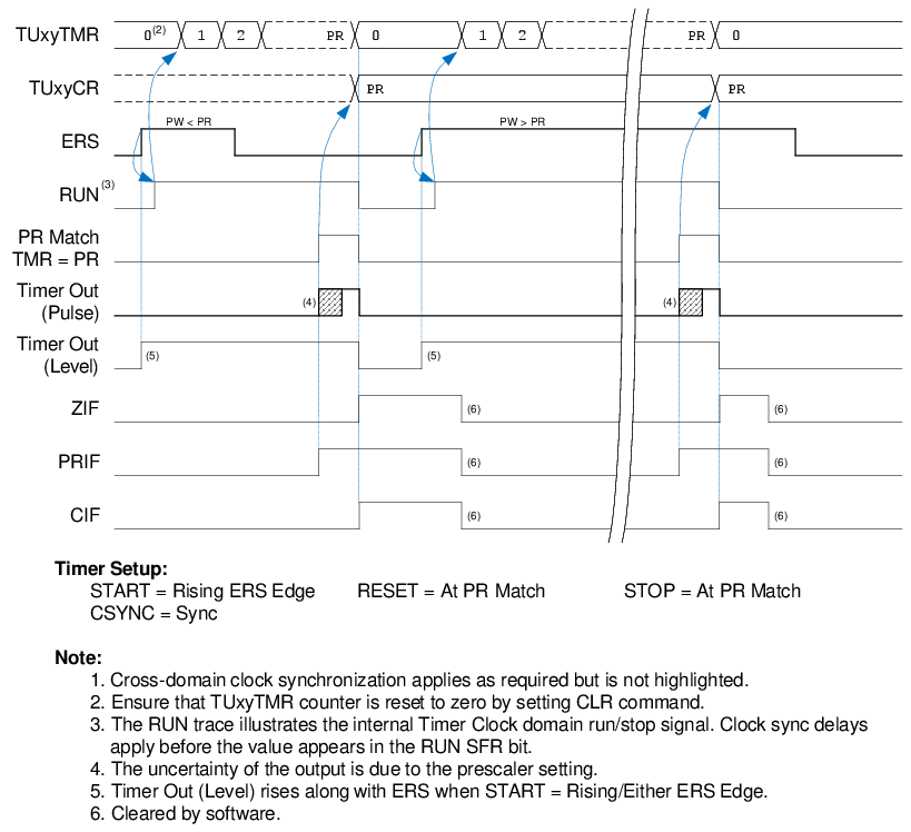
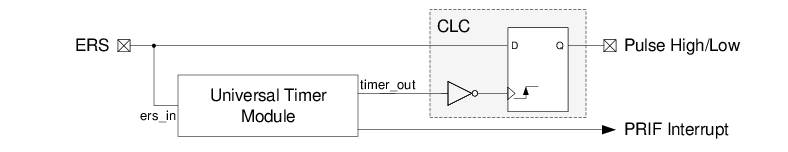
The timer can be configured to detect a minimum pulse width when combined with a D Flip Flop in a CLC peripheral as per the settings shown in Table 2-8. The output of the timer is connected to the clock input of the D flip flop. Set and Clear of the D flip flop are tied low. The D input of the flip flop is connected to the same ERS input signal. This setup is shown in Figure 2-11.
| Timer Setting | Value |
|---|---|
| START | Rising ERS Edge |
| RESET | At PR Match |
| STOP | At PR Match |
| CSYNC (Clock Sync) | Sync |
| EPOL (ERS Polarity) |
True Level (to test for high pulse width) Inverted Level (to test for low pulse width) |
| OSEN (One-shot) |
Enabled (for one-shot) Disabled (for auto-repeat) |
| PR (Period Register) | Desired minimum pulse width |
When the input rises (from 0 to 1), the counter will begin to count. When PR match occurs, PRIF is set and an output pulse will occur. This is shown in Figure 2-10. This output pulse triggers the clock input of the D Flip Flop in the CLC peripheral to latch the state of D-input. If the pulse width is longer than the PR match period, the D flip flop will latch a high output. If the pulse width is shorter than the PR match period, the D flip flop will latch a low output.
1 and invert
the output of the CLC.