The timer can be configured to measure the period of the ERS signal as per the settings shown in Table 2-6.
| Timer Setting | Value |
|---|---|
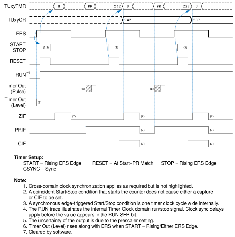
| START | Rising ERS Edge |
| RESET | At Start + PR Match |
| STOP | Rising ERS Edge |
| CSYNC (Clock Sync) | Sync |
| EPOL (ERS Polarity) |
True Level (to measure rising-to-rising edges period) Inverted Level (to measure falling-to-falling edges period) |
| OSEN (One-shot) |
Enabled (for single measurement) Disabled (for continuous measurement) |
| PR (Period Register) | Desired Period Value |
When the ERS input rises (changes from 0 to 1), the counter resets to zero and begins counting. When the counter resets to zero, ZIF interrupt occurs. At the next rising edge, the counter value is captured into the TUxyCR capture register, where it can be read by software, and CIF is set. This is shown in Figure 2-8.
Because Start, Stop and Reset all occur at the same time, the counter is immediately reset and resumes counting. The software must read the captured value before the next input period is complete or the TUxyCR capture register will be overwritten with the next measurement. Alternatively, use One-Shot mode by setting the OSEN bit to stop after the first measurement and prevent a data overrun.
The CIF interrupt occurs when each measurement completes. Technically, the CIF interrupt and timer capture should occur with the Stop condition that is present when first starting, but is withheld because it does not mark a completed measurement.