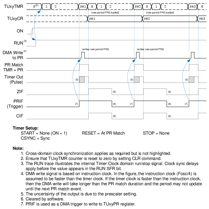
The Direct Memory Access (DMA) peripheral can be used in conjunction with the timer to create a variable output pulse period that updates at rollover. The timer can be configured as per the settings shown in Table 2-4. A DMA channel is configured to read from a program flash table with post-increment and rollover without termination. The PRIF timer interrupt can be used as a trigger to start the DMA transfer. Refer to TB3164: Direct Memory Access on 8-Bit PIC Microprocessor to learn how to configure the DMA peripheral.
| Timer Setting | Value |
|---|---|
| START | None (ON = 1) |
| RESET | At PR Match |
| STOP | None |
| CSYNC (Clock Sync) | Sync |
| PR (Period Register) | First period value; updated by DMA subsequently |
The counter counts until the first PR match occurs and then rolls over to zero and continues counting. At PR match, the PRIF interrupt triggers the DMA to transfer the new period value into the PR register and arms the loading of the new period value. The effective PR register is updated with the new period value at the next PR match. This is shown in Figure 2-5. Clock synchronization delays apply.
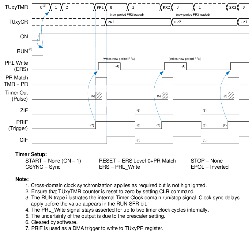
If an immediate PR load is desired, then set:
- ERS = PRL_Write
- RESET = ERS Level-0 + PR Match
- EPOL =
1(Inverted Polarity)
In this case, as soon as the DMA triggers a transfer and writes to the TUxyPRL register, it arms the update. The write to the TUxyPRL register also generates a high ERS input which can be used to force a timer reset and load the new PR value. This is shown in Figure 2-6.