| Timer Setting | Value |
|---|---|
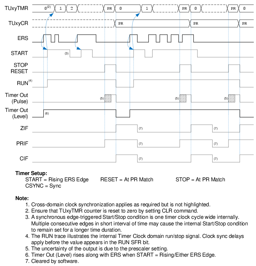
| START | Rising ERS Edge |
| RESET | At PR Match |
| STOP | At PR Match |
| CSYNC (Clock Sync) | Sync |
| EPOL (ERS Polarity) |
True Level (to trigger to rising edge) Inverted Level (to trigger to falling edge) |
| PR (Period Register) | Desired minimum pulse width |
Initialize the timer counter by setting the CLR command. When the input rises (changes from 0 to 1), the counter will begin counting. Any more input changes will be ignored unless a rising edge occurs near the PR match, which will override the Stop condition, reset the counter, and continue counting. This is shown in Figure 2-12.
If OM = 1 (level), the output will be a pulse of duration
(timer clock period) * (PR+1), beginning immediately upon the input edge, and continuing
as long as ERS toggles. If OM = 0 (pulse), a pulse will appear some
time after the original rising edge when the PR match occurs, and possibly repeat
periodically.
1 or START = Either ERS Edge.