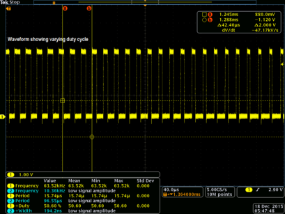
The analog low-pass filter could be a simple passive RC-filter for instance. The filter removes the high PWM base frequency and lets through the analog signal. The filter crossover frequency must be chosen high enough to not alter the analog signal of interest. At the same time, it must be as low as possible to minimize the ripple from the PWM base frequency. The higher the base frequency is, the easier it is to attenuate the base frequency and thereby minimize the signal ripple. The selection of resolution versus base frequency is thus an application dependent trade-off.
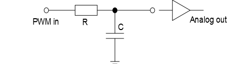
If the analog signal is fed to a low-impedance input, a buffer amplifier should be connected between the filter output and the load. This will prevent the load from discharging the capacitor and creating ripple voltages.