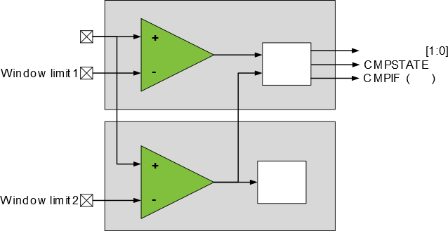
Each AC (i.e., ACx) can be configured to work together with another comparator (i.e., ACy) in Window mode. In this mode, a voltage range (the window) is defined, and the selected comparator indicates whether an input signal is within this range or not.
The WINSEL bit field in the Control B (ACn.CTRLB) register selects which ACy instance is connected to the current comparator (ACx) to create the window comparator. The user is responsible for configuring the MUXPOS and MUXNEG bit fields in the MUX Control (ACn.MUXCTRL) register for ACx and ACy, so they match the setup in the figure below. Note that the MUXPOS bit field in the ACn.MUXCTRL register of both ACs must be configured to the same pin.
The status of the input signal is reported by the Window State (WINSTATE) flags in the Status (ACn.STATUS) register. The status can be:
- Above the window - the input signal is above the upper limit
- Inside the window - the input signal is between the lower and upper limits
- Below the window - the input signal is below the lower limit
- Above the window - the interrupt/event is issued when the input signal is above the upper limit
- Inside the window - the interrupt/event is issued when the input signal is between the lower and upper limits
- Below the window - the interrupt/event is issued when the input signal is below the lower limit
- Outside the window - the interrupt/event is issued when the input signal is not between the lower and upper limits
The CMPSTATE bit is ‘1’ when the Window state matches the
selected Interrupt Mode (INTMODE) bit field and ‘0’ otherwise.
The window interrupt is enabled by writing a ‘1’ to the
Analog Comparator Interrupt Enable (CMP) bit in the Interrupt Control (ACn.INTCTRL)
register.