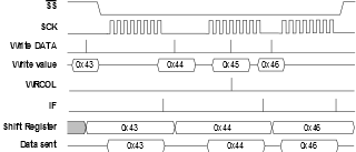
In Normal mode, the SPI peripheral will remain Idle as long as the SS pin is driven high. In this state, the software may update the contents of the DATA register, but the data will not be shifted out by incoming clock pulses on the SCK pin until the SS pin is driven low. If the SS pin is driven low, the client will start to shift out data on the first SCK clock pulse. When one byte has been completely shifted, the SPI Interrupt Flag (IF) in SPIn.INTFLAGS is set.
The user application may continue placing new data to be sent into the DATA register before reading the incoming data. New bytes to be sent cannot be written to the DATA register before the entire transfer has been completed. A premature write will be ignored, and the hardware will set the Write Collision (WRCOL) flag in SPIn.INTFLAGS.
When the SS pin is driven high, the SPI logic is halted, and the SPI client will not receive any new data. Any partially received packet in the shift register will be lost.
Figure 1 shows a transmission sequence in Normal mode. Notice how the value 0x45 is written to the DATA register but never transmitted.