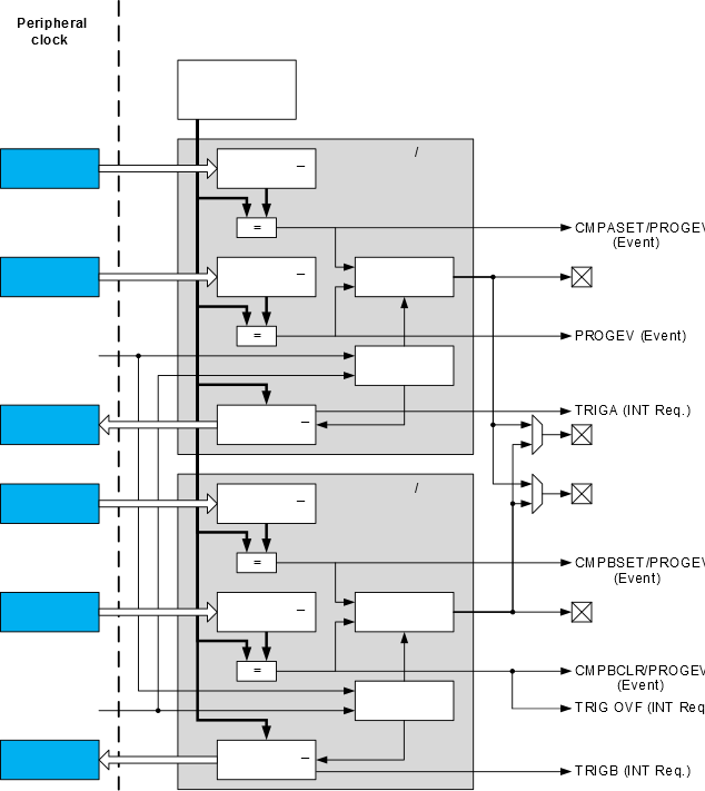
The TCD core is asynchronous to the peripheral clock. The timer/counter consists of two compare/capture units, each with a separate waveform output. There are also two extra waveform outputs, which can be equal to the output from one of the units. For each compare/capture unit, there is a pair of compare registers which is stored in the respective peripheral (TCDn.CMPASET, TCDn.CMPACLR, TCDn.CMPBSET, TCDn.CMPBCLR) registers.
During normal operation, the counter value is continuously compared to the compare registers. This is used to generate both interrupts and events.
The TCD can use the input events in ten different input modes, selected separately for the two input events. The input mode defines how the input events will affect the outputs and where in the TCD cycle the counter must go when an event occurs.
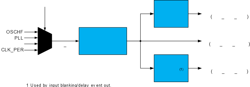
The TCD synchronizer clock is separate from the other module clocks, enabling faster synchronization between the TCD domain and the I/O domain.
The total prescaling for the counter is:
The delay prescaler is used to prescale the clock utilized for the input blanking/delayed event output functionality. The prescaler can be configured independently, allowing separate range and accuracy settings from the counter functionality. The synchronization prescaler and counter prescaler can be configured from the Control A (TCDn.CTRLA) register, while the delay prescaler can be configured from the Delay Control (TCDn.DLYCTRL) register.