Figure 1. SPI - Timing Requirements in
Host Mode
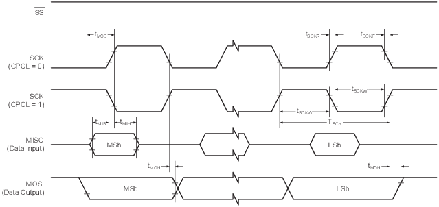
| Symbol | Description | Min. | Typ.✝ | Max. | Unit | Condition |
|---|---|---|---|---|---|---|
| fSCK * | SCK clock frequency | — | — | 10 | MHz | |
| TSCK * | SCK period | 100 | — | — | ns | |
| tSCKW | SCK high/low width | — | 0.5×TSCK | — | ns | |
| tSCKR | SCK rise time | — | 2.7 | — | ns | |
| tSCKF | SCK fall time | — | 2.7 | — | ns | |
| tMIS | MISO setup to SCK | — | 10 | — | ns | |
| tMIH | MISO hold after SCK | — | 10 | — | ns | |
| tMOS | MOSI setup to SCK | — | 0.5×TSCK | — | ns | |
| tMOH | MOSI hold after SCK | — | 1.0 | — | ns | |
|
✝ Data in the “Typ.” column is at TA = 25°C and VDD = 3.0V unless otherwise specified. These parameters are for design guidance only and are not tested. * These parameters are characterized but not tested in production. |
||||||
Figure 2. SPI - Timing Requirements in
Client Mode
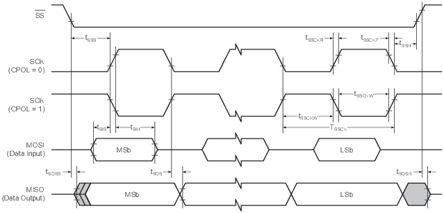
| Symbol | Description | Min. | Typ.✝ | Max. | Unit | Condition |
|---|---|---|---|---|---|---|
| fSSCK * | Client SCK clock frequency | — | — | 5 | MHz | |
| TSSCK * | Client SCK period | 4×TCLK_PER | — | — | ns | |
| tSSCKW * | SCK high/low width | 2×TCLK_PER | — | — | ns | |
| tSSCKR * | SCK rise time | — | — | 1600 | ns | |
| tSSCKF * | SCK fall time | — | — | 1600 | ns | |
| tSIS * | MOSI setup to SCK | 3.0 | — | — | ns | |
| tSIH * | MOSI hold after SCK | TCLK_PER | — | — | ns | |
| tSSS * | SS setup to SCK | 21 | — | — | ns | |
| tSSH * | SS hold after SCK | 20 | — | — | ns | |
| tSOS | MISO setup to SCK | — | 8.0 | — | ns | |
| tSOH | MISO hold after SCK | — | 13 | — | ns | |
| tSOSS | MISO setup after SS low | — | 11 | — | ns | |
| tSOSH | MISO hold after SS low | — | 8.0 | — | ns | |
|
✝ Data in the “Typ.” column is at TA = 25°C and VDD = 3.0V unless otherwise specified. These parameters are for design guidance only and are not tested. * These parameters are characterized but not tested in production. |
||||||