The ADC needs a time twarm_up to initialize after writing a '1' to the ENABLE bit in the Control A (ADCn.CTRLA) register. This delay can be implemented manually in code or by configuring the Initialization Delay (INITDLY) bit field in the Control D (ADCn.CTRLD) register to a value ≥ twarm_up x fCLK_ADC. Refer to the Electrical Characteristics section for further information.
Once the initialization is finished, a conversion is started by writing a
‘1’ to the ADC Start Conversion (STCONV) bit in the Command
(ADCn.COMMAND) register. This bit is ‘1’ as long as the conversion is in
progress. The STCONV bit will be set during a conversion and cleared once the conversion is
complete.
If a different input channel is selected while a conversion is in progress, the ADC will finish the current conversion before changing the channel.
Depending on the accumulator setting, the conversion result is a single
sample, or an accumulation of samples. Once the triggered operation is finished, the Result
Ready (RESRDY) flag in the Interrupt Flags (ADCn.INTFLAGS) register is set. The
corresponding interrupt vector is executed if the Result Ready Interrupt Enable (RESRDY)
bit in the Interrupt Control (ADCn.INTCTRL) register is ‘1’ and the Global
Interrupt Enable bit is ‘1’.
The RESRDY interrupt flag in the ADCn.INTFLAGS register will be set even if the specific interrupt is disabled, allowing software to check for any finished conversion by polling the flag. A conversion can thus be triggered without causing an interrupt upon completion.
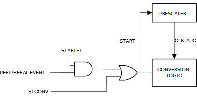
Alternatively, a conversion can be triggered by an event. This is enabled by
writing a ‘1’ to the Start Event Input (STARTEI) bit in the Event Control
(ADCn.EVCTRL) register. Any incoming event routed to the ADC through the Event System
(EVSYS) will trigger an ADC conversion. This provides a method to start conversions with
predictable intervals or at specific conditions.
The ADC will trigger a conversion on the rising edge of an event signal. When an event occurs, the STCONV bit in the ADCn.COMMAND register is set and it will be cleared when the conversion is complete. Refer to Figure 1.
In Free-Running mode, the first conversion is started by writing a
‘1’ to the STCONV bit in the ADCn.COMMAND register. A new conversion
cycle is started immediately after the previous conversion cycle has completed. A completed
conversion will set the RESRDY flag in the ADCn.INTFLAGS register.