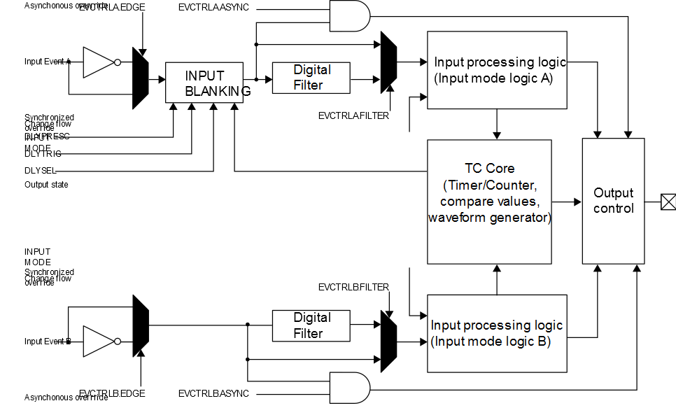
The TCD has two inputs connected to the Event System: Input A and input B. Each input has a functionality connected to the corresponding output (WOA and WOB). This functionality is controlled by the Event Control (TCDn.EVCTRLA and TCDn.EVCTRLB) registers and the Input Control (TCDn.INPUTCTRLA and TCDn.INPUTCTRLB) registers.
To enable the input events, write a ‘1’ to the Trigger Event Input
Enable (TRIGEI) bit in the corresponding Event Control (TCDn.EVCTRLA or TCDn.EVCTRLB)
register. The inputs will be used as a Fault detect by default, but they can also be
used as a capture trigger. To enable a capture trigger, write a ‘1’ to
the ACTION bit in the corresponding Event Control (TCDn.EVCTRLA or TCDn.EVCTRLB)
register. The INPUTMODE bit field in the corresponding Input Control (TCDn.INPUTCTRLA or
TCDn.INPUTCTRLB) register must be written to ‘0’ to disable Fault
detect.
There are ten different input modes for Fault detection. The two inputs have the same functionality, except for input blanking, which is only supported by input A. Input blanking is configured by the Delay Control (TCDn.DLYCTRL) register and the Delay Value (TCDn.DLYVAL) register.
The inputs are connected to the Event System. The connections between the event source and the TCD input must be configured in the Event System.
There is a delay of two/three clock cycles on the TCD synchronizer clock between receiving the input event, processing it, and overriding the outputs. If using the asynchronous event detection, the outputs will override instantly outside the input processing.