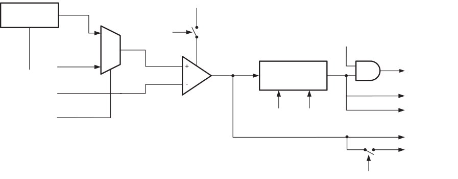
Only one Internal reference (1.1V – Bandgap) will be connected to the positive input of the AC. For using Bandgap reference voltage as positive input to AC , it is advisable that Bandgap reference is first enabled by writing '1' to ACSRA.ACBG and then selected by writing '1' to ACSRB.ACPMUX . The output of comparator output can be set to trigger the Timer/Counter1 Input Capture function. In addition, the comparator can trigger a separate interrupt, exclusive to the Analog Comparator. The user can select Interrupt triggering on comparator output rise, fall or toggle. A block diagram of the comparator and its surrounding logic is shown below.
The Power Reduction ADC bit in the Power Reduction Register (PRR.PRADC) must be written to '0' in order to be able to use the ADC input MUX.