Left Adjustment for
ADC Result Readout
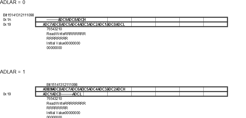
The ADLAR bit
affects the presentation of the ADC conversion result in the ADC Data Register.
Write one to ADLAR to left adjust the result. Otherwise, the result is right
adjusted. Changing the ADLAR bit will affect the ADC Data Register immediately,
regardless of any ongoing conversions.
ADC Auto Trigger
Source [n = 2:0]
If ADATE in ADCSRA is written to one, the value of these bits selects
which source will trigger an ADC conversion. If ADATE is cleared, the ADTS[2:0]
settings will have no effect. A conversion will be triggered by the rising edge
of the selected Interrupt Flag. Note that switching from a trigger source that
is cleared to a trigger source that is set, will generate a positive edge on the
trigger signal. If ADEN in ADCSRA is set, this will start a conversion.
Switching to Free Running mode (ADTS[2:0]=0) will not cause a trigger event,
even if the ADC Interrupt Flag is set.
Table 1. ADC Auto Trigger Source
Selection
| ADTS[2:0] |
Trigger Source |
| 000 |
Free Running mode |
| 001 |
Analog Comparator |
| 010 |
External Interrupt Request 0 |
| 011 |
Timer/Counter 0 Compare Match A |
| 100 |
Timer/Counter 0 Overflow |
| 101 |
Timer/Counter 0 Compare Match B |
| 110 |
Pin Change Interrupt 0 Request |
| 111 |
Timer/Counter 0 Capture Event |