During reset, all I/O Registers are set to their initial values, and the program starts execution from the Reset Vector. The instruction placed at the Reset Vector must be an Relative Jump instruction (RJMP) to the reset handling routine. If the program never enables an interrupt source, the Interrupt Vectors are not used, and regular program code can be placed at these locations. The circuit diagram in the next shows the reset logic. Electrical parameters of the reset circuitry are defined in section System and Reset Characteristics.
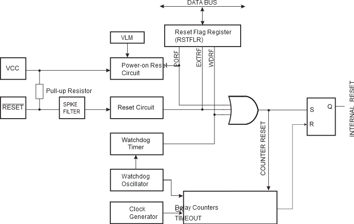
The I/O ports of the AVR are immediately reset to their initial state when a reset source goes active. This does not require any clock source to be running.
After all reset sources have gone inactive, a delay counter is invoked, stretching the internal reset. This allows the power to reach a stable level before normal operation starts.