The RSWDT is supplied by VDDCORE. The RSWDT is initialized with default values on processor reset or on a power-on sequence and is disabled (its default mode) under such conditions.
The RSWDT must not be enabled if the WDT is disabled.
The Main RC oscillator divided clock is selected if the Main RC oscillator is already enabled by the application (CKGR_MOR.MOSCRCEN = 1) or if the WDT is driven by the Slow RC oscillator.
The RSWDT is built around a 12-bit down counter, which is loaded with a slow clock value other than that of the slow clock in the WDT, defined in the WDV (Watchdog Counter Value) field of the Mode Register (RSWDT_MR). The RSWDT uses the slow clock divided by 128 to establish the maximum watchdog period to be 16 seconds (with a typical slow clock of 32.768 kHz).
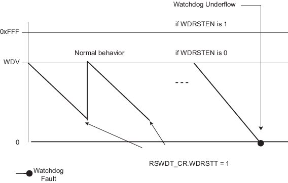
After a processor reset, the value of RSWDT_MR.WDV is 0xFFF, corresponding to the maximum value of the counter with the external reset generation enabled (RSWDT_MR.WDRSTEN = 1 after a backup reset). This means that a default watchdog is running at reset, i.e., at power-up.
If the watchdog is restarted by writing into the Control Register (RSWDT_CR), the RSWDT_MR must not be programmed during a period of time of three slow clock periods following the RSWDT_CR write access. Programming a new value in the RSWDT_MR automatically initiates a restart instruction.
RSWDT_MR can be written only once. Only a processor reset resets it. Writing RSWDT_MR reloads the timer with the newly programmed mode parameters.
In normal operation, the user reloads the watchdog at regular intervals before the timer underflow occurs, by setting bit RSWDT_CR.WDRSTT. The watchdog counter is then immediately reloaded from the RSWDT_MR and restarted, and the slow clock 128 divider is reset and restarted. The RSWDT_CR is write-protected. As a result, writing RSWDT_CR without the correct hard-coded key has no effect. If an underflow does occur, the “wdt_fault” signal to the Reset Controller is asserted if RSWDT_MR.WDRSTEN is set. Moreover, WDUNF (Watchdog Underflow) is set in the Status Register (RSWDT_SR).
The status bits WDUNF and WDERR trigger an interrupt, provided the WDFIEN bit is set in the RSWDT_MR. The signal “wdt_fault” to the Reset Controller causes a Watchdog reset if the WDRSTEN bit. For details, refer to the section “Reset Controller (RSTC)”. In this case, the processor and the RSWDT are reset, and the WDUNF and WDERR flags are reset.
If a reset is generated, or if RSWDT_SR is read, the status bits are reset, the interrupt is cleared, and the “wdt_fault” signal to the reset controller is deasserted
Writing RSWDT_MR reloads and restarts the down counter.
The RSWDT is disabled after any power-on sequence.
While the processor is in Debug state or in Idle mode, the counter may be stopped depending on the value programmed for the WDIDLEHLT and WDDBGHLT bits in the RSWDT_MR.