The temperature sensor is internally connected to channel index 11.
The AFEC manages temperature measurement in several ways. The different methods of measurement depend on the configuration bits TRGEN in the AFEC_MR and CH11 in AFEC_CHSR.
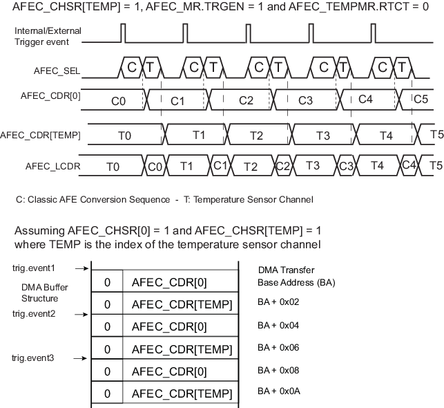
Temperature measurement can be triggered at the same rate as other channels by enabling the conversion channel 11.
If AFEC_CHSR.CH11 is enabled, the temperature sensor analog cell is switched on. If a user sequence is used, the last converted channel of the sequence is always the temperature sensor channel.
A manual start can be performed only if AFEC_MR.TRGEN is disabled. When AFEC_CR.START is set, the temperature sensor channel conversion is scheduled together with the other enabled channels (if any). The result of the conversion is placed in an internal register that can be read in the AFEC_CDR (AFEC_CSELR must be programmed accordingly prior to reading AFEC_CDR) and the associated flag EOC11 is set in the AFEC_ISR.
The channel of the temperature sensor is periodically converted together with the other enabled channels and the result is placed into AFEC_LCDR and an internal register (can be read in AFEC_CDR). Thus the temperature conversion result is part of the Peripheral DMA Controller buffer. The temperature channel can be enabled/disabled at any time, but this may not be optimal for downstream processing.
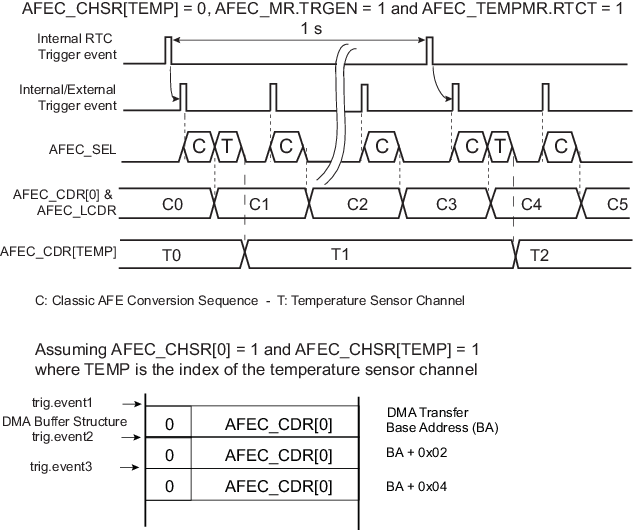
The temperature factor has a slow variation rate and may be different from other conversion channels. As a result, the AFEC allows a different way of triggering temperature measurement when AFEC_TEMPMR.RTCT is set but AFEC_CHSR.CH11 is cleared.
In this configuration, the measurement is triggered every second by means of an internal trigger generated by the RTC. This trigger is always enabled and independent of the triggers used for other channels. In this mode of operation, the temperature sensor is only powered for a period of time covering startup time and conversion time.
Every second, a conversion is scheduled for channel 11 but the result of the conversion is only uploaded to an internal register read by means of AFEC_CDR, and not to AFEC_LCDR. Therefore, the temperature channel is not part of the Peripheral DMA Controller buffer; only the enabled channel are kept in the buffer. The end of conversion of the temperature channel is reported by means of the EOC11 flag in AFEC_ISR.
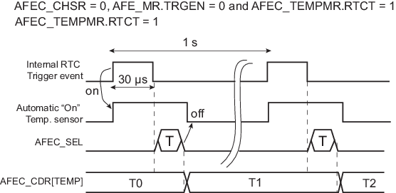
If RTCT is set and TRGEN is cleared, then all channels are disabled (AFEC_CHSR = 0) and only channel 11 is converted at a rate of one conversion per second.
This mode of operation, when combined with Sleep mode operation, provides a low-power mode for temperature measurement assuming there is no other AFE conversion to schedule at a higher sampling rate or no other channel to convert.
Moreover, it is possible to raise a flag only if there is predefined change in the temperature measurement. The user can define a range of temperature or a threshold in AFEC_TEMPCWR and the mode of comparison in AFEC_TEMPMR. These values define the way the TEMPCHG flag will be raised in AFEC_ISR.
The TEMPCHG flag can be used to trigger an interrupt if there is an update/modification to be made in the system resulting from a temperature change.
In any case, if temperature sensor measurement is configured, the temperature can be read at any time in AFEC_CDR (AFEC_CSELR must be programmed accordingly prior to reading AFEC_CDR) .