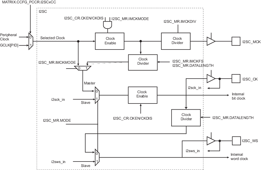
The generation of clocks in the I2SC is described in figure ”Mono”.
In Slave mode, the serial clock and word select clock are driven by an external master. I2SC_CK and I2SC_WS pins are inputs.
In Master mode, the user can configure the master clock, serial clock, and word select clock through the I2SC_MR. I2SC_MCK, I2SC_CK, and I2SC_WS pins are outputs and MCK is used to derive the I2SC clocks.
In Master mode, if the peripheral clock frequency is higher than 96 MHz, the GCLK[PID] from PMC must be selected as I2SC input clock by writing a ‘1’ in the I2SCxCC bit of the CCFG_PCCR register. Refer to the section “Bus Matrix (MATRIX)” for more details.
Audio codecs connected to the I2SC pins may require a master clock (I2SC_MCK) signal with a frequency multiple of the audio sample frequency (fs), such as 256fs. When the I2SC is in Master mode, writing a ’1’ to I2SC_MR.IMCKMODE outputs MCK as master clock to the I2SC_MCK pin, and divides MCK to create the internal bit clock, output on the I2SC_CK pin. The clock division factor is defined by writing to I2SC_MR.IMCKFS and I2SC_MR.DATALENGTH, as described in the I2SC_MR.IMCKFS field description.
The master clock (I2SC_MCK) frequency is (2×16 × (IMCKFS + 1)) / (IMCKDIV + 1) times the sample frequency (fs), i.e., I2SC_WS frequency.
Example: If the sampling rate is 44.1 kHz with an I2S master clock (I2SC_MCK) ratio of 256, the core frequency must be an integer multiple of 11.2896 MHz. Assuming an integer multiple of 4, the IMCKDIV field must be configured to 4; the field IMCKFS must then be set to 31.
The serial clock (I2SC_CK) frequency is 2 × Slot Length times the sample frequency (fs), where Slot Length is defined in the following table.
| I2SC_MR.DATALENGTH | Word Length | Slot Length |
|---|---|---|
| 0 | 32 bits | 32 |
| 1 | 24 bits | 32 if I2SC_MR.IWS = 0 24 if I2SC_MR.IWS = 1 |
| 2 | 20 bits | |
| 3 | 18 bits | |
| 4 | 16 bits | 16 |
| 5 | 16 bits compact stereo | |
| 6 | 8 bits | 8 |
| 7 | 8 bits compact stereo |
If a master clock output is not required, the MCK clock is used as I2SC_CK by clearing I2SC_MR.IMCKMODE. Alternatively, if the frequency of the MCK clock used is a multiple of the required I2SC_CK frequency, the I2SC_MCK to I2SC_CK divider can be used with the ratio defined by writing the I2SC_MR.IMCKFS field.
The I2SC_WS pin is used as word select as described in section “I2S Reception and Transmission Sequence”.