The Enhanced Resolution mode is enabled when AFEC_EMR.RES is set to 13-bit resolution or higher. In this mode, the AFEC trades conversion performance for accuracy by averaging multiple samples, thus providing a digital low-pass filter function. The resolution mode selected determines the oversampling, which represents the performance reduction factor.
To increase the accuracy by averaging multiple samples, some noise must be present in the input signal. The noise level should be between one and two LSB peak-to-peak to get good averaging performance.
The following table summarizes the oversampling ratio depending on the resolution mode selected.
| Resolution Mode | Oversampling Ratio |
|---|---|
| 13-bit | 4 |
| 14-bit | 16 |
| 15-bit | 64 |
| 16-bit | 256 |
Free Run mode is not supported if Enhanced Resolution mode is used.
The selected oversampling ratio applies to all enabled channels except the temperature sensor channel if triggered by an RTC event. See Temperature Sensor.
The average result is valid into an internal register (read by means of the AFEC_CDR) only if EOCx (x corresponding to the index of the channel) flag is set in AFEC_ISR and OVREx flag is cleared in the AFEC_OVER. The average result is valid for all channels in the AFEC_LCDR only if DRDY is set and GOVRE is cleared in the AFEC_ISR.
Note that the AFEC_CDR is not buffered. Therefore, when an averaging sequence is ongoing, the value in this register changes after each averaging sample. However, overrun flags in the AFEC_OVER rise as soon as the first sample of an averaging sequence is received. Thus the previous averaged value is not read, even if the new averaged value is not ready.
As a result, when an overrun flag rises in the AFEC_OVER, this indicates only that the previous unread data is lost. It does not indicate that this data has been overwritten by the new averaged value, as the averaging sequence concerning this channel can still be on-going.
The samples can be defined in different ways for the averaging function depending on the configuration of AFEC_EMR.STM and AFEC_MR.USEQ.
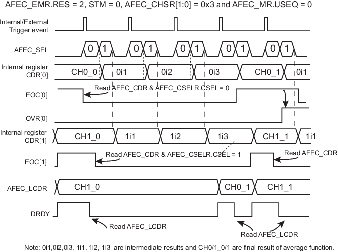
When USEQ is cleared, there are two possible ways to generate the averaging through the trigger event. If AFEC_EMR.STM is cleared, every trigger event generates one sample for each enabled channel, as described in the figure below. Therefore, four trigger events are requested to get the result of averaging if RES = 2.
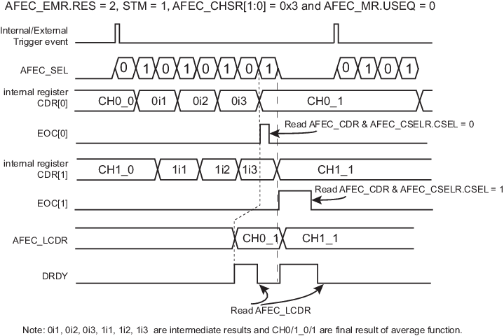
If AFEC_EMR.STM is set and AFEC_MR.USEQ is cleared, the sequence to be converted, defined in the AFEC_CHSR, is automatically repeated n times, where n corresponds to the oversampling ratio defined AFEC_EMR.RES. As a result, only one trigger is required to get the result of the averaging function as shown in the figure below.
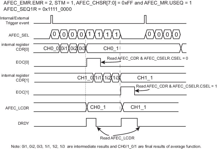
When USEQ is set, the user can define the channel sequence to be converted by configuring AFEC_SEQxR and AFEC_CHER so that channels are not interleaved during the averaging period. Under these conditions, a sample is defined for each end of conversion as described in the figure below.
Therefore, if the same channel is configured to be converted four times consecutively and AFEC_EMR.RES = 2, the averaging result is placed in the corresponding channel internal data register (read by means of the AFEC_CDR) and the AFEC_LCDR for each trigger event.
In this case, the AFE real sample rate remains the maximum AFE sample rate divided by 4.
When USEQ is set and the RES field enables the Enhanced Resolution mode, it is important to note that the user sequence must be a sequence being an integer multiple of 4 (i.e., the number of the enabled channel in the Channel Status register (AFEC_CHSR) must be an integer multiple of 4 and the AFEC_SEQxR must be a series of 4 times the same channel index).