The Receiver Timeout provides support in handling variable-length frames. This feature detects an idle condition on the RXD line. When a timeout is detected, US_CSR.TIMEOUT rises and can generate an interrupt, thus indicating to the driver an end of frame.
The timeout delay period (during which the receiver waits for a new character) is programmed in the TO field of the Receiver Timeout register (US_RTOR). If TO is written to ‘0’, the Receiver Timeout is disabled and no timeout is detected. US_CSR.TIMEOUT remains at ‘0’. Otherwise, the receiver loads a 16-bit counter with the value programmed in US_RTOR.TO. This counter is decremented at each bit period and reloaded each time a new character is received. If the counter reaches 0, TIMEOUT rises. Then, the user can either:
- Stop the counter clock until a new character is received. This is performed by writing a ‘1’ to US_CR.STTTO. In this case, the idle state on RXD before a new character is received will not provide a timeout. This prevents having to handle an interrupt before a character is received and allows waiting for the next idle state on RXD after a frame is received.
- Obtain an interrupt while no character is received. This is performed by writing a ‘1’ to the RETTO (Reload and Start Timeout) bit in the US_CR. In this case, the counter starts counting down immediately from the value TO. This generates a periodic interrupt so that a user timeout can be handled, for example when no key is pressed on a keyboard.
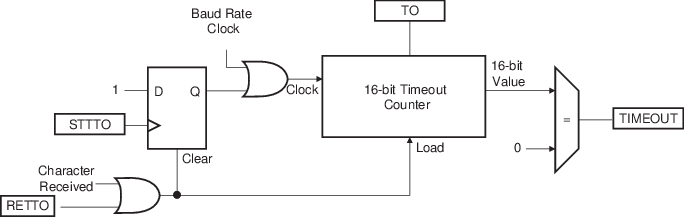
The following figure shows the block diagram of the Receiver Timeout feature.
The following table provides the maximum timeout period for some standard baud rates.
| Baud Rate (bit/s) | Bit Time (μs) | Timeout (ms) |
|---|---|---|
| 600 | 1,667 | 109,225 |
| 1,200 | 833 | 54,613 |
| 2,400 | 417 | 27,306 |
| 4,800 | 208 | 13,653 |
| 9,600 | 104 | 6,827 |
| 14,400 | 69 | 4,551 |
| 19,200 | 52 | 3,413 |
| 28,800 | 35 | 2,276 |
| 38,400 | 26 | 1,704 |
| 56,000 | 18 | 1,170 |
| 57,600 | 17 | 1,138 |
| 200,000 | 5 | 328 |