The wakeup inputs, WKUPx, can be programmed to perform a wakeup of the core power supply. Each input can be enabled by writing a ‘1’ to the corresponding bit, WKUPENx, in the Wakeup Inputs register (SUPC_WUIR). The wakeup level can be selected with the corresponding polarity bit, WKUPTx, also located in SUPC_WUIR.
The resulting signals are wired-ORed to trigger a debounce counter, which is programmed with SUPC_WUMR.WKUPDBC. This field selects a debouncing period of 3, 32, 512, 4,096 or 32,768 slow clock cycles. The duration of these periods corresponds, respectively, to about 100 μs, about 1 ms, about 16 ms, about 128 ms and about 1 second (for a typical slow clock frequency of 32 kHz). Programming SUPC_WUMR.WKUPDBC to 0 selects an immediate wakeup, i.e., an enabled WKUP pin must be active according to its polarity during a minimum of one slow clock period to wake up the core power supply.
If an enabled WKUP pin is asserted for a duration longer than the debouncing period, a wakeup of the core power supply is started and the signals, WKUP0 to WKUPx as shown in “Wakeup Sources”, are latched in SUPC_SR. This allows the user to identify the source of the wakeup. However, if a new wakeup condition occurs, the primary information is lost. No new wakeup can be detected since the primary wakeup condition has disappeared.
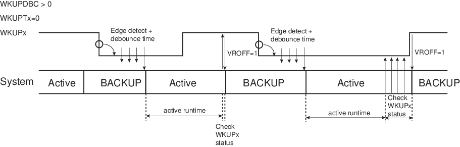
Before instructing the system to enter Backup mode, if the field SUPC_WUMR.WKUPDBC > 0, it must be checked that none of the WKUPx pins that are enabled for a wakeup (exit from Backup mode) holds an active polarity. This is checked by reading the pin status in the PIO Controller. If SUPC_WUIR.WKUPENx=1 and the pin WKUPx holds an active polarity, the system must not be instructed to enter Backup mode.