Figure 1. High Speed MultiMedia Memory Card Bus Topology
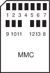
The High Speed MultiMedia Card communication is based on a 13-pin serial bus interface. It has three communication lines and four supply lines.
| Pin Number | Name | Type(1) | Description | HSMCI Pin Name(2) (Slot z) |
|---|---|---|---|---|
| 1 | DAT[3] | I/O/PP | Data | MCDz3 |
| 2 | CMD | I/O/PP/OD | Command/response | MCCDz |
| 3 | VSS1 | S | Supply voltage ground | VSS |
| 4 | VDD | S | Supply voltage | VDD |
| 5 | CLK | O | Clock | MCCK |
| 6 | VSS2 | S | Supply voltage ground | VSS |
| 7 | DAT[0] | I/O/PP | Data 0 | MCDz0 |
| 8 | DAT[1] | I/O/PP | Data 1 | MCDz1 |
| 9 | DAT[2] | I/O/PP | Data 2 | MCDz2 |
Notes:
- 1.I: Input, O: Output, PP: Push/Pull, OD: Open Drain, S: Supply
- 2.When several HSMCI (x HSMCI) are embedded in a product, MCCK refers to HSMCIx_CK, MCCDA to HSMCIx_CDA, MCDAy to HSMCIx_DAy.
Figure 2. MMC Bus Connections (One Slot)
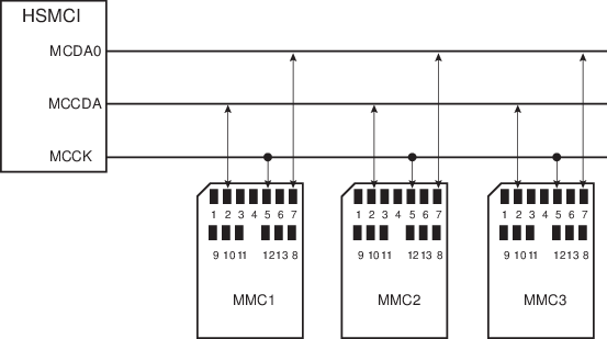
Note: When several HSMCI (x HSMCI) are embedded in a product, MCCK refers to HSMCIx_CK,
MCCDA to HSMCIx_CDA MCDAy to HSMCIx_DAy.
Figure 3. SD Memory Card Bus Topology
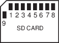
The SD Memory Card bus includes the signals listed in the table below.
| Pin Number | Name | Type(1) | Description | HSMCI Pin Name(2) (Slot z) |
|---|---|---|---|---|
| 1 | CD/DAT[3] | I/O/PP | Card detect/ Data line Bit 3 | MCDz3 |
| 2 | CMD | PP | Command/response | MCCDz |
| 3 | VSS1 | S | Supply voltage ground | VSS |
| 4 | VDD | S | Supply voltage | VDD |
| 5 | CLK | O | Clock | MCCK |
| 6 | VSS2 | S | Supply voltage ground | VSS |
| 7 | DAT[0] | I/O/PP | Data line Bit 0 | MCDz0 |
| 8 | DAT[1] | I/O/PP | Data line Bit 1 or Interrupt | MCDz1 |
| 9 | DAT[2] | I/O/PP | Data line Bit 2 | MCDz2 |
Notes:
- 1.I: input, O: output, PP: Push Pull, OD: Open Drain.
- 2.When several HSMCI (x HSMCI) are embedded in a product, MCCK refers to HSMCIx_CK, MCCDA to HSMCIx_CDA, MCDAy to HSMCIx_DAy.
Figure 4. SD Card Bus Connections with One Slot
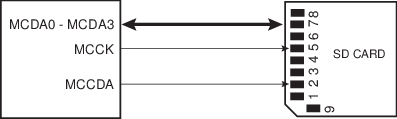
Note: When several HSMCI (x HSMCI) are embedded in a product, MCCK refers to HSMCIx_CK,
MCCDA to HSMCIx_CDA MCDAy to HSMCIx_DAy.
When the HSMCI is configured to operate with SD memory cards, the width of the data bus can be selected in the HSMCI_SDCR. Clearing the SDCBUS bit in this register means that the width is one bit; setting it means that the width is four bits. In the case of High Speed MultiMedia cards, only the data line 0 is used. The other data lines can be used as independent PIOs.