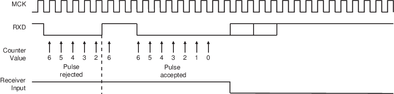
The demodulator is based on the IrDA Receive filter comprised of an 8-bit down counter which is loaded with the value programmed in US_IF. When a falling edge is detected on the RXD pin, the Filter Counter starts counting down at the peripheral clock speed. If a rising edge is detected on the RXD pin, the counter stops and is reloaded with US_IF. If no rising edge is detected when the counter reaches 0, the input of the receiver is driven low during one bit time.
The following figure illustrates the operations of the IrDA demodulator.
The programmed value in the US_IF register must always meet the following criterion:
tperipheral clock × (IRDA_FILTER + 3) < 1.41 μs
As the IrDA mode uses the same logic as the ISO7816, note that the FI_DI_RATIO field in US_FIDI must be set to a value higher than 0 in order to ensure IrDA communications operate correctly.