MediaLB supports four data transport methods: synchronous stream data, asynchronous packet data, control message data and isochronous data. Synchronous stream data is transmitted in a broadcast fashion, where the only response allowed by an Rx Device is ReceiverReady (MLBS default). Control and asynchronous transport methods are packet based and support only one Rx Device at a time. Control and asynchronous transmissions require start and end commands to delineate the packets. Isochronous data can be broadcast if all Rx Devices do not use the status response of ReceiverBusy. Otherwise, isochronous transmissions must be to a single Rx Device.
Control and Asynchronous
Both the control and asynchronous commands define the boundaries of a packet message and work similarly. The following discussion on control packets also applies to asynchronous packets with the commands changed to the asynchronous versions.
For control packets, the ControlStart command is sent by the Tx Device at the start of a message. After the first quadlet of the message, middle quadlets will use the ControlContinue command. For the last quadlet of the packet, the Tx Device uses the ControlEnd command. If the command sequence is received out of order, the Rx Device sends the status response of ReceiverProtocolError in the next quadlet of the logical channel.
If the Tx Device must abort the packet while it’s being transmitted, the ControlBreak command is sent. Assuming a message is to be retransmitted after the ControlBreak command is sent, the message must be restarted from the beginning (cannot resume with the ControlContinue command).
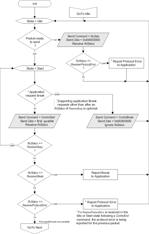
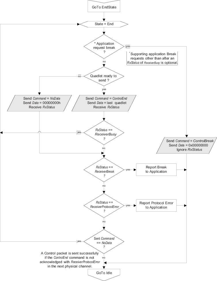
The protocol flow for a Tx Device is illustrated in Figure 1 through Figure 3. Although these diagrams illustrate control packet transmission, they also apply to asynchronous packets where the commands that start with Control are replaced by Async. The data transfer blocks (slanted rectangle shapes) occur only during a physical channel (PCn) associated with the logical channel defined by a single ChannelAddress.
The flow diagram contains four states: Idle, Start, Continue, and End. Each state uses a different command when sending the data. The Idle state is the starting point, waiting for the application to initiate a packet transfer. When a quadlet is ready to be transferred, the flow diagram moves to the Start state.
Note: If a ControlEnd command is sent in the physical channel preceding a ReceiverProtocolError RxStatus (in either the Idle or Start state), the ReceiverProtocolError status response must be assigned to the previous packet transmitted. Alternatively, a status response of ReceiverProtocolError (in either the Idle or Start state) must not be assigned to the previous packet transmitted unless ControlEnd was sent in the preceding physical channel.
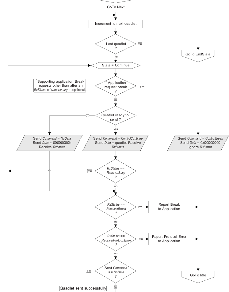
Once a quadlet has been sent successfully, the flow diagram moves to the Continue state, depicted in Figure 2, and stays there until all but the last quadlet has been transmitted. The last quadlet is transmitted in the End state, which is depicted in Figure 3.
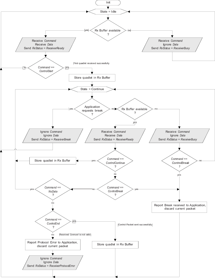
The protocol flow for an Rx Device is illustrated in Figure 4. This flow diagram consists of only two states: Idle and Continue. The Idle state is the starting point where the Rx Device is waiting for a packet start command. Once a start command has been received (ControlStart or AsyncStart), the flow diagram moves to the Continue state. The reception of a ControlEnd command completes the transfer and moves the flow diagram back to the Idle state, where it waits for the next packet.
The protocol flow for an Rx Device, as described in Figure 4, should be used as a reference for standard MediaLB Devices. According to this flow, a ReceiverProtocolError status response may be sent by an Rx Device only in the Continue state; however, more enhanced MediaLB Devices can also conduct protocol checks in the Idle state. In this case, a ReceiverProtocolError status response could be sent for example, if a logical channel is setup for control data and an isochronous or synchronous command is received. Protocol checks in the Continue state may be expanded beyond the flow shown in Figure 4 when required by specific implementations.
Synchronous
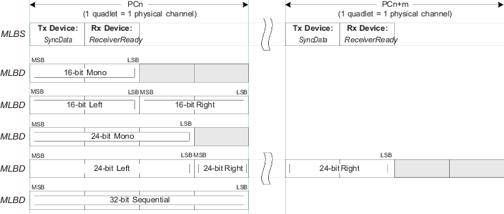
Synchronous stream data is sent in a continuous and broadcast fashion, without block information. Therefore, receiving Devices must not respond to the synchronous command; thereby leaving RxStatus in the ReceiverReady state (logic low). For 3-pin MediaLB, the required pull-down on MLBS leaves this signal in the ReceiverReady command when no synchronous data is transmitted on the MLBD line.
Figure 5 illustrates the synchronous data formats for MediaLB. For stereo 24-bit data, two physical channels (PCn) are needed per frame where the data is packed and left-justified in the two quadlets. In the 32-bit sequential format, data fills the entire quadlet with the internal data format determined by the system implementor.
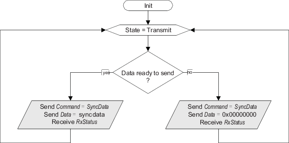
The synchronous flow for a Tx Device is illustrated in Figure 6. The data transfer blocks (slanted rectangle shapes) occur only during a physical channel (PCn) associated with the logical channel defined by a single ChannelAddress. The flow diagram contains only one state: Transmit. Once a channel has been initialized, the Transmit state is entered. If a Tx Device has no data to transmit, it must still send the SyncData command and set the actual data to a safe value, such as all zeros. To stop sending synchronous data, the logical channel must be eliminated (ChannelAddress removed from MediaLB).
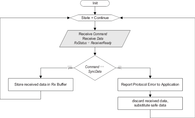
The synchronous flow for an Rx Device is illustrated in Figure 7. The flow diagram also contains only one state, Continue, where the Rx Device waits for data from the Tx Device. No command other than SyncData is expected or allowed. When the SyncData command is detected, the corresponding data quadlet sent with the command is received and stored in the Rx buffer. Any command received, other than SyncData, is a ProtocolError and should be reported to the application. Furthermore, the data quadlet received with the invalid command is discarded and replaced with a safe value.
Since the default bus state is ReceiverReady, the Rx Device must not drive the MLBS line with RxStatus since ReceiverReady is the only allowable response for synchronous data. The system stops the transfer of synchronous data by eliminating the logical channel (ChannelAddress) from the bus. If an Rx Device does not receive its ChannelAddress in the frame, it should assume that the channel is not setup yet, or that the logical channel has been eliminated and should respond accordingly (for example, mute outputs).
Isochronous
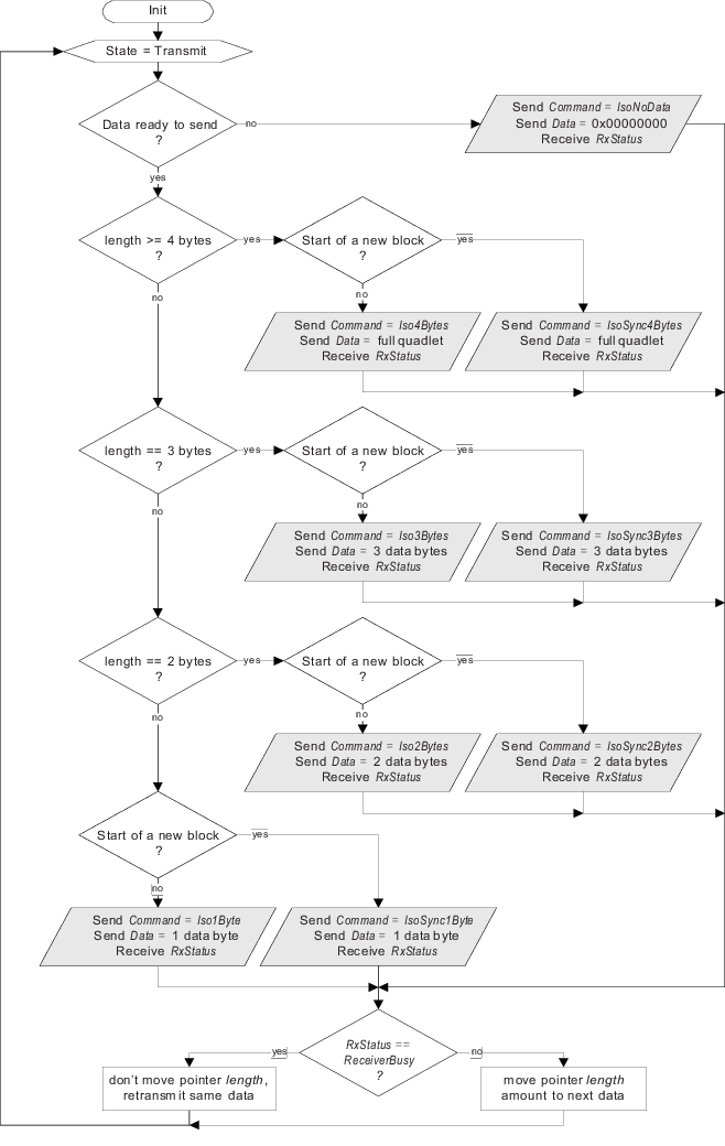
Isochronous data is sent in a streaming fashion, similar to synchronous data. However, the isochronous commands indicate the start of a block and how many bytes are valid in the concurrent transmitted quadlet. Valid bytes are left-justified in the quadlet, as illustrated in Figure 8. When isochronous data is being transported (channel active), but no data is available for the current quadlet, the IsoNoData command is sent by the Tx Device.
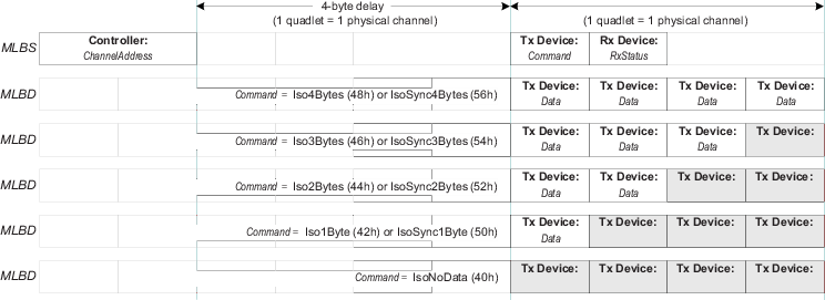
The isochronous flow for a Tx Device is illustrated in Figure 9. The data transfer blocks (slanted rectangle shapes) occur only during a physical channel (PCn) associated with the logical channel defined by a single ChannelAddress. Similar to the synchronous flow, isochronous data immediately starts transmitting. When data exists from the application, the IsoSync?Bytes commands are used to indicate the start of a block, which provides alignment information to the Rx Device. The Iso?Bytes commands indicate the middle of a block of data. The definition of block for isochronous data is outside the scope of this document. For physical channels that transfer less than four bytes, the Rx Device must only use/store the number of valid bytes, and ignore the unused portion.
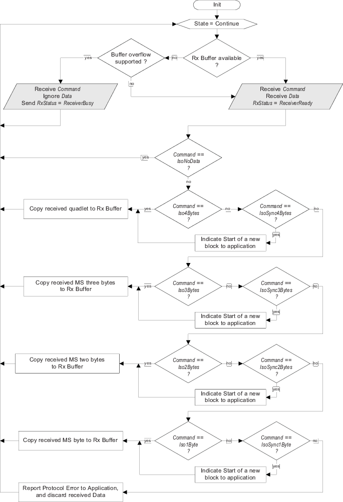
The isochronous flow for an Rx Device is illustrated in Figure 10. The NoData command indicates that the channel is not setup yet. Once an isochronous channel is setup, the Rx Device continually receives the channel data, similar to synchronous data. The only two valid responses for an isochronous channel are ReceiverBusy, and the default bus state of ReceiverReady. Although Rx Devices can respond with ReceiverBusy, its use should be minimized, since Tx Devices may not be able to store much isochronous data that gets backed up due to the ReceiverBusy responses. If any Rx Device uses ReceiverBusy, then only one Rx Device is allowed. If all targeted Rx Devices do not drive RxStatus (default ReceiverReady response), then the isochronous stream can support multiple Rx Devices (broadcast).