The USART supports five Parity modes. The PAR field also enables Multidrop mode, see “Multidrop Mode”. Even and odd parity bit generation and error detection are supported. The configuration is done in US_MR.PAR.
If even parity is selected, the parity generator of the transmitter drives the parity bit to 0 if a number of 1s in the character data bit is even, and to 1 if the number of 1s is odd. Accordingly, the receiver parity checker counts the number of received 1s and reports a parity error if the sampled parity bit does not correspond. If odd parity is selected, the parity generator of the transmitter drives the parity bit to 1 if a number of 1s in the character data bit is even, and to 0 if the number of 1s is odd. Accordingly, the receiver parity checker counts the number of received 1s and reports a parity error if the sampled parity bit does not correspond. If the mark parity is used, the parity generator of the transmitter drives the parity bit to 1 for all characters. The receiver parity checker reports an error if the parity bit is sampled to 0. If the space parity is used, the parity generator of the transmitter drives the parity bit to 0 for all characters. The receiver parity checker reports an error if the parity bit is sampled to 1. If parity is disabled, the transmitter does not generate any parity bit and the receiver does not report any parity error.
The following table shows an example of the parity bit for the character 0x41 (character ASCII “A”) depending on the configuration of the USART. Because there are two bits set to 1 in the character value, the parity bit is set to ‘1’ when the parity is odd, or configured to ‘0’ when the parity is even.
| Character | Hexadecimal | Binary | Parity Bit | Parity Mode |
|---|---|---|---|---|
| A | 0x41 | 0100 0001 | 1 | Odd |
| A | 0x41 | 0100 0001 | 0 | Even |
| A | 0x41 | 0100 0001 | 1 | Mark |
| A | 0x41 | 0100 0001 | 0 | Space |
| A | 0x41 | 0100 0001 | None | None |
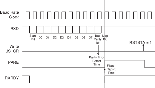
When the receiver detects a parity error, it sets US_CSR.PARE (Parity Error). PARE can be cleared by writing a ‘1’ to the RSTSTA bit the US_CR. The following figure illustrates the parity bit status setting and clearing.