The baud rate generator provides the bit period clock, also named the baud rate clock, to both the receiver and the transmitter.
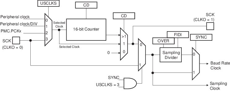
The baud rate generator clock source is selected by configuring the USCLKS field in the USART Mode register (US_MR) to one of the following:
- The peripheral clock
- A division of the peripheral clock, where the divider is product-dependent, but generally set to 8
- A processor/peripheral independent clock source fully programmable provided by PMC (PCK)
- The external clock, available on the SCK pin
The baud rate generator is based upon a 16-bit divider, which is configured using the CD field of the Baud Rate Generator register (US_BRGR). If CD is configured to ‘0’, the baud rate generator does not generate any clocks. If CD is configured to ‘1’, the divider is bypassed and becomes inactive.
If the external SCK clock is selected, the duration of the low and high levels of the signal provided on the SCK pin must be longer than a peripheral clock period. The frequency of the signal provided on SCK must be at least 3 times lower than the frequency provided on the peripheral clock in USART mode (field USART_MODE differs from 0xE or 0xF), or 6 times lower in SPI mode (field USART_MODE equals 0xE or 0xF).
If PMC PCK is selected, the baud rate is independent of the processor/peripheral clock and thus processor/peripheral clock frequency can be changed without affecting the USART transfer. The PMC PCKx frequency must always be three times lower than the peripheral clock frequency.
If PMC PCK is selected (USCLKS = 2) and the SCK pin is driven (CLKO = 1), the value of US_BRGR.CD must be greater than 1.