Conversions of the active analog channels are started with a software or hardware trigger. The software trigger is provided by writing a ‘1’ to the bit START in the Control Register (AFEC_CR).
The hardware trigger can be one of the TIOA outputs of the Timer Counter channels, PWM Event line, or the external trigger input of the AFEC (ADTRG). The hardware trigger is selected with AFEC_MR.TRGSEL. The selected hardware trigger is enabled with AFEC_MR.TRGEN
The minimum time between two consecutive trigger events must be strictly greater than the duration of the longest conversion sequence according to configuration of registers AFEC_MR, AFEC_CHSR, AFEC_SEQ1R, AFEC_SEQ2R.
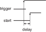
If a hardware trigger is selected, the start of a conversion is triggered after a delay starting at each rising edge of the selected signal. Due to asynchronous handling, the delay may vary in a range of two peripheral clock periods to one AFE clock period. This delay varies from trigger to trigger and so introduces a jitter error leading to a reduced Signal-to-Noise ratio performance.
If one of the TIOA outputs is selected, the corresponding Timer Counter channel must be programmed in Waveform mode.
Only one start command is necessary to initiate a conversion sequence on all the channels. The AFEC hardware logic automatically performs the conversions on the active channels, then waits for a new request. The Channel Enable (AFEC_CHER) and Channel Disable (AFEC_CHDR) registers permit the analog channels to be enabled or disabled independently.
If the AFEC is used with a DMA, only the transfers of converted data from enabled channels are performed and the resulting data buffers should be interpreted accordingly.