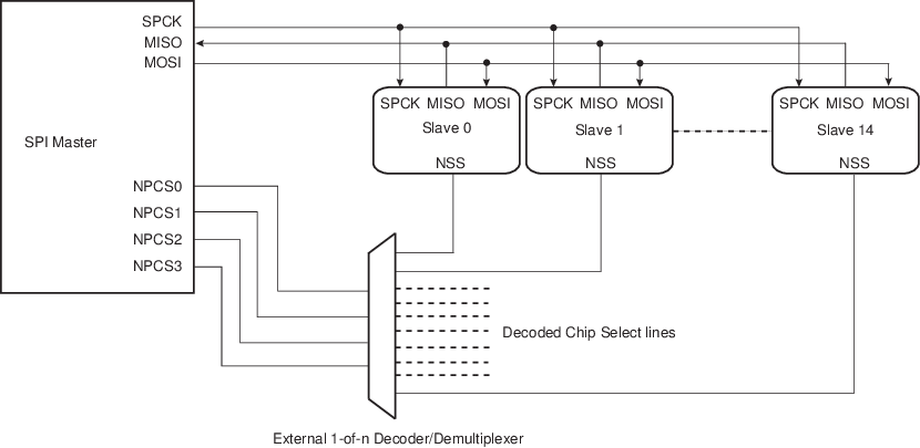
The user can program the SPI to operate with up to 15 slave peripherals by decoding the four chip select lines, NPCS0 to NPCS3 with an external decoder/demultiplexer (see figure below). This can be enabled by setting SPI_MR.PCSDEC.
When operating without decoding, the SPI makes sure that in any case only one chip select line is activated, i.e., one NPCS line driven low at a time. If two bits are defined low in a PCS field, only the lowest numbered chip select is driven low.
When operating with decoding, the SPI directly outputs the value defined by the PCS field on the NPCS lines of either SPI_MR or SPI_TDR (depending on PS).
As the SPI sets a default value of 0xF on the chip select lines (i.e., all chip select lines at 1) when not processing any transfer, only 15 peripherals can be decoded.
The SPI has four chip select registers (SPI_CSR0...SPI_CSR3). As a result, when external decoding is activated, each NPCS chip select defines the characteristics of up to four peripherals. As an example, SPI_CRS0 defines the characteristics of the externally decoded peripherals 0 to 3, corresponding to the PCS values 0x0 to 0x3. Consequently, the user has to make sure to connect compatible peripherals on the decoded chip select lines 0 to 3, 4 to 7, 8 to 11 and 12 to 14. The following figure shows this type of implementation.
If SPI_CSRx.CSAAT bit is used, with or without the DMAC, the Mode Fault detection for NPCS0 line must be disabled. This is not needed for all other chip select lines since Mode Fault detection is only on NPCS0.