The comparator continuously compares its counter value with the channel period defined by CPRD in the PWM Channel Period Register (PWM_CPRDx) and the duty-cycle defined by CDTY in the PWM Channel Duty Cycle Register (PWM_CDTYx) to generate an output signal OCx accordingly.
The different properties of the waveform of the output OCx are:
- the clock selection. The channel counter is clocked by one of the clocks provided by the clock generator described in the previous section. This channel parameter is defined in the CPRE field of the PWM Channel Mode Register (PWM_CMRx). This field is reset at ‘0’.
- the waveform period. This channel parameter is defined in the
CPRD field of the PWM_CPRDx register.
If the waveform is left-aligned, then the output
waveform period depends on the counter source clock and can be calculated:
By using the
PWM peripheral clock divided by a given prescaler value “X” (where X = 2PREA is 1, 2, 4, 8, 16, 32, 64, 128, 256, 512, or 1024).
The resulting period formula is:
- the waveform duty-cycle. This channel parameter is defined in the CDTY field of the PWM_CDTYx register.
If the waveform is left-aligned, then:
- the waveform polarity. At the beginning of the period, the
signal can be at high or low level. This property is defined in the CPOL bit of
PWM_CMRx. By default, the signal starts by a low level. The DPOLI bit in PWM_CMRx defines the
PWM polarity when the channel is disabled (CHIDx = 0 in PWM_SR). For more details,
see the figure Waveform Properties.
- DPOLI = 0: PWM polarity when the channel is disabled is the same as the one defined for the beginning of the PWM period.
- DPOLI = 1: PWM polarity when the channel is disabled is inverted compared to the one defined for the beginning of the PWM period.
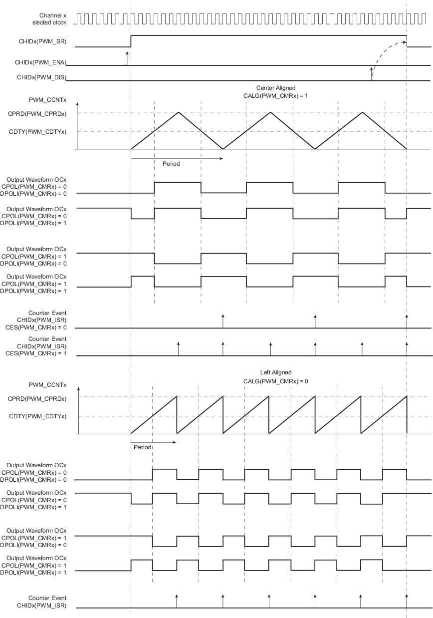
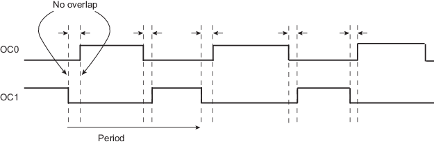
- the waveform alignment. The output waveform can be left- or center-aligned. Center-aligned waveforms can be used to generate non-overlapped waveforms. This property is defined in the CALG bit of PWM_CMRx. The default mode is left-aligned.
When center-aligned, the channel counter increases up to CPRD and decreases down to 0. This ends the period.
When left-aligned, the channel counter increases up to CPRD and is reset. This ends the period.
Thus, for the same CPRD value, the period for a center-aligned channel is twice the period for a left-aligned channel.
Waveforms are fixed at 0 when:
- CDTY = CPRD and CPOL = 0 (Note that if TRGMODE = MODE3, the PWM waveform switches to 1 at the external trigger event (see Cycle-By-Cycle Duty Mode)).
- CDTY = 0 and CPOL = 1
Waveforms are fixed at 1 (once the channel is enabled) when:
- CDTY = 0 and CPOL = 0
- CDTY = CPRD and CPOL = 1 (Note that if TRGMODE = MODE3, the PWM waveform switches to 0 at the external trigger event (see Cycle-By-Cycle Duty Mode)).
The waveform polarity must be set before enabling the channel. This immediately affects the channel output level.
Modifying CPOL in PWM Channel Mode Register while the channel is enabled can lead to an unexpected behavior of the device being driven by PWM.
In addition to generating the output signals OCx, the comparator generates interrupts depending on the counter value. When the output waveform is left-aligned, the interrupt occurs at the end of the counter period. When the output waveform is center-aligned, the bit CES of PWM_CMRx defines when the channel counter interrupt occurs. If CES is set to ‘0’, the interrupt occurs at the end of the counter period. If CES is set to ‘1’, the interrupt occurs at the end of the counter period and at half of the counter period.
The figure below illustrates the counter interrupts depending on the configuration.