In Fast Flash Programming mode, the device is in a specific test mode. Only a certain set of pins is significant. The rest of the PIOs are used as inputs with a pullup. The crystal oscillator is in Bypass mode, an external clock must be provided on the XIN pin.
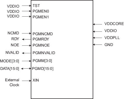
Figure 1. 16-bit Parallel Programming Interface
| Signal Name | Function | Type | Active Level | Comments |
|---|---|---|---|---|
| Power | ||||
| VDDIO | I/O Lines Power Supply | Power | – | – |
| VDDCORE | Core Power Supply | Power | – | – |
| VDDPLL | PLL Power Supply | Power | – | – |
| GND | Ground | Ground | – | – |
| Clocks | ||||
| XIN | Main Clock Input | Input | – | – |
| Test | ||||
| TST | Test Mode Select | Input | High | Must be connected to VDDIO |
| PGMEN0 | Test Mode Select | Input | Low | Must be connected to VDDIO |
| PGMEN1 | Test Mode Select | Input | High | Must be connected to VDDIO |
| PIO | ||||
| PGMNCMD | Valid command available | Input | Low | Pulled-up input at reset |
| PGMRDY | 0: Device is busy 1: Device is ready for a new command |
Output | High | Pulled-up input at reset |
| PGMNOE | Output Enable (active high) | Input | Low | Pulled-up input at reset |
| PGMNVALID | 0: DATA[15:0]
is in input mode 1: DATA[15:0] is in output mode |
Output | Low | Pulled-up input at reset |
| PGMM[3:0] | Specifies DATA type (see Table 1) | Input | – | Pulled-up input at reset |
| PGMD[15:0] | Bidirectional data bus | Input/Output | – | Pulled-up input at reset |