The AHB block manages data exchange between local channel data buffers within the MLB and the system memory buffer.
To support system memory buffering, a ping-pong memory structure is implemented on a per-channel basis using 128-bit descriptors for AHB Descriptor Table (ADT) entries.
Each logical channel is assigned a separate 128-bit descriptor, defining the data buffers in the system memory used by the DMA interface for that channel. The descriptors are stored at fixed addresses in the external CTR.
AHB Descriptor Table
The following table provides an overview of field definitions for ADT entries.
| Field | No. of Bits | Description | Accessibility |
|---|---|---|---|
| CE | 1 | Channel enable: 0 = Disabled 1 = Enabled |
r,w,u (1) |
| LE | 1 | Endianess select: 0 = Big Endian 1 = Little Endian |
r,w |
| PG | 1 | Page pointer. Software initializes to zero, hardware writes thereafter. 0 = Ping buffer 1 = Pong buffer |
r,w,u (1) |
| RDY1 | 1 | Buffer ready bit for ping buffer page: 0 = Not ready 1 = Ready |
r,w |
| RDY2 | 1 | Buffer ready bit for pong buffer page: 0 = Not ready 1 = Ready |
r,w |
| DNE1 | 1 | Buffer done bit for ping buffer page: 0 = Not done 1 = Done |
r,u (1),c0 |
| DNE2 | 1 | Buffer done bit for pong buffer page: 0 = Not done 1 = Done |
r,u (1),c0 |
| ERR1 | 1 | AHB error response detected for ping buffer page: 0 = No error 1 = Error |
r,u (1),c0 (2) |
| ERR2 | 1 | AHB error response detected for pong buffer page: 0 = No error 1 = Error |
r,u (1),c0 (2) |
| PS1 | 1 | Packet start bit for ping buffer page: 0 = No packet start 1 = Packet start Reserved for synchronous and isochronous channels. |
r,w,u (1) (both Tx and Rx) |
| PS2 | 1 | Packet start bit for pong buffer page: 0 = No packet start 1 = Packet start Reserved for synchronous and isochronous channels. |
r,w,u (1) (both Tx and Rx) |
| MEP1 | 1 | Most Ethernet Packet (MEP) indicator for ping buffer page: 0 = Not MEP 1 = MEP MEP1 only valid for the first page of a segmented buffer. Reserved for control, synchronous and isochronous channels. |
Rsvd for Tx r,u (1),c0 (2) for Rx |
| MEP2 | 1 | MEP packet indicator for pong buffer page: 0 = not MEP 1 = MEP MEP2 only valid for the first page of a segmented buffer. Reserved for control, synchronous and isochronous channels. |
Reserved for Tx r,u (1),c0 (2) for Rx |
| BD1(2) | 11 to 13 | Buffer depth for ping buffer page: 11 or 12-bits for asynchronous and control channels. 13-bits for synchronous and isochronous channels. |
r,w |
| BD2(2) | 11 to 13 | Buffer depth for pong buffer page: 11 or 12-bits for asynchronous and control channels. 13-bits for synchronous and isochronous channels. |
r,w |
| BA1 | 32 | Buffer base address for ping buffer page | r,w |
| BA2 | 32 | Buffer base address for pong buffer page | r,w |
| Reserved | varies | Software writes a zero to all Reserved bits when the entry is initialized. The reserved bits are Read-only after initialization. | r,w,u (1) |
- 1.“u” means “Updated periodically by hardware”.
- 2.“c0” means “Cleared by writing a 0”.
- 3.The buffer depth (BD1 and BD2) for synchronous channels must consider if Multi-Frame per Sub-buffer mode is enabled.
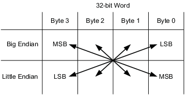
Data exchange across the AHB interface can be configured as Little Endian (LE = 1) or Big Endian (LE = 0). The following figure provides an overview of the endian options, chosen by an ADT descriptor field.
The following figure shows an example of the ping-pong system memory structure. This system memory structure is similar for all channel types and shows the relationship between the BAn, BDn, and PG descriptor fields.
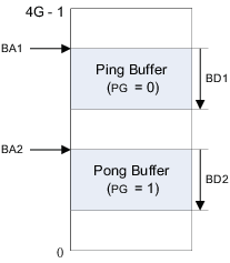
Each ADT entry holds a 32-bit BAn field which defines the start of each ping or pong buffer within system memory. The BDn field is used to indicate the size for the respective ping or pong page. The maximum size is 2k-entries for asynchronous and control channels; 8k-entries for isochronous and synchronous channels.
AHB Synchronous Channel Descriptors
Table 2 shows the format for a synchronous ADT entry. The field definitions are defined in Table 3. Each synchronous channel buffer can be up to 8k-bytes deep.
| Bit Offset | 15 | 14 | 13 | 12 | 11 | 10 | 9 | 8 | 7 | 6 | 5 | 4 | 3 | 2 | 1 | 0 |
|---|---|---|---|---|---|---|---|---|---|---|---|---|---|---|---|---|
| 0 | CE | LE | PG | Reserved | ||||||||||||
| 16 | Reserved | |||||||||||||||
| 32 | RDY1 | DNE1 | ERR1 | BD1[12:0] | ||||||||||||
| 48 | RDY2 | DNE2 | ERR2 | BD2[12:0] | ||||||||||||
| 64 | BA1[15:0] | |||||||||||||||
| 80 | BA1[31:16] | |||||||||||||||
| 96 | BA2[15:0] | |||||||||||||||
| 112 | BA2[31:16] | |||||||||||||||
AHB Isochronous Channel Descriptors
The isochronous buffering scheme allows each ping or pong buffer to contain a single block or a multiple number of blocks. For this reason, the isochronous buffer depth (BDn) must be defined in terms of an integer number (n) and block size (BS) (e.g. BDn = n x (BS + 1) - 1).
Table 3 shows the format for an isochronous ADT entry. The field definitions are defined in Table 4. Each isochronous channel buffer can be up to 8k-bytes deep.
| Bit Offset | 15 | 14 | 13 | 12 | 11 | 10 | 9 | 8 | 7 | 6 | 5 | 4 | 3 | 2 | 1 | 0 |
|---|---|---|---|---|---|---|---|---|---|---|---|---|---|---|---|---|
| 0 | CE | LE | PG | Reserved | ||||||||||||
| 16 | Reserved | |||||||||||||||
| 32 | RDY1 | DNE1 | ERR1 | BD1[12:0] | ||||||||||||
| 48 | RDY2 | DNE2 | ERR2 | BD2[12:0] | ||||||||||||
| 64 | BA1[15:0] | |||||||||||||||
| 80 | BA1[31:16] | |||||||||||||||
| 96 | BA2[15:0] | |||||||||||||||
| 112 | BA2[31:16] | |||||||||||||||
AHB Asynchronous and Control Channel Descriptors
Every asynchronous and control packet adheres to the Port Message Protocol (PMP), which designates the first two bytes of each packet as the packet length (PML). Each packet must be no more than 2048 bytes.
Software must set the buffer ready bit (RDYn) for each buffer as it programs the DMA. As hardware processes each buffer, it sets the done bit (DNEn) and generates an interrupt to inform HC. When hardware finishes processing a buffer it can begin processing another buffer if RDYn is set. The application is responsible for setting up and configuring the channel buffer descriptor prior to every DMA access on the channel.
Two packet modes are supported by hardware for programming the DMA, single-packet mode and multiple-packet mode.
Single-packet Mode
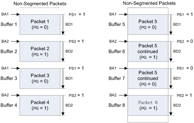
The single-packet mode asynchronous and control buffering scheme supports a maximum of one packet per buffer (e.g. ping or pong). Both non-segmented and segmented data packets are allowed while using single-packet mode.
Non-segmented packets are exchanged when only one buffer (e.g. ping or pong) is needed for packet transfer. Segmented packets are exchanged when a single packet is too long for one buffer and the packet must span multiple buffers. The following figure shows the memory space usage for both non-segmented and segmented asynchronous or control packets along with the packet start bit (PSn). While using single-packet mode, buffer done (DNEn) is set in hardware when a packet is done or the buffer is full.
shows the format for single-packet mode asynchronous and control ADT entries. The field definitions are defined in Table 4.
| Bit Offset | 15 | 14 | 13 | 12 | 11 | 10 | 9 | 8 | 7 | 6 | 5 | 4 | 3 | 2 | 1 | 0 |
|---|---|---|---|---|---|---|---|---|---|---|---|---|---|---|---|---|
| 0 | CE | LE | PG | Reserved | ||||||||||||
| 16 | Reserved | |||||||||||||||
| 32 | RDY1 | DNE1 | ERR1 | PS1 | MEP1 | BD1[10:0] | ||||||||||
| 48 | RDY2 | DNE2 | ERR2 | PS2 | MEP2 | BD2[10:0] | ||||||||||
| 64 | BA1[15:0] | |||||||||||||||
| 80 | BA1[31:16] | |||||||||||||||
| 96 | BA2[15:0] | |||||||||||||||
| 112 | BA2[31:16] | |||||||||||||||
Multiple-packet Mode
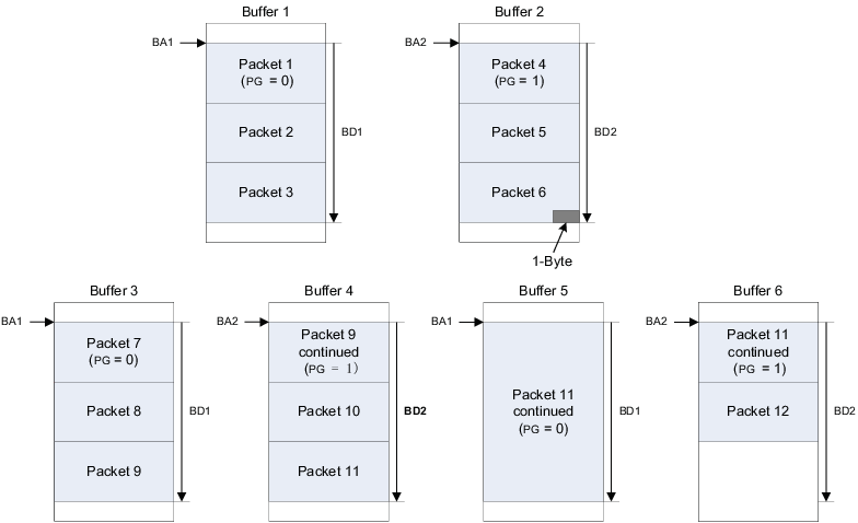
The multiple-packet mode asynchronous and control buffering scheme supports more than one packet per system memory buffer, as shown in the following figure. Multiple- packet mode reduces the interrupt rate for packet channels at the cost of increasing buffering and latency.
For Tx packet channels in multiple-packet mode, software sets the packet start bit (PSn) for every buffer. Setting PSn informs hardware that the first two bytes of the buffer contains the port message length (PML) of the first packet. After the first packet, hardware keeps track of where packets start and end within the current buffer. Software should not write to PSn while the buffer is active (RDYn = 1 and DNEn = 0). For Tx packet channels, the buffer is done (DNEn= 1) when the last byte of the last packet in the buffer is read from system memory. Software should set the buffer depth to contain the exact number of complete packets for that buffer. Segmented buffers are not supported for Tx packet channels in multiple-packet mode.
For Rx packet channels in multiple-packet mode, PSn has no meaning and should be ignored. Software is responsible for keeping track of where each packet starts and ends within the multiple-packet buffer via the packet PML. The buffer done bit (DNEn) is set in hardware for Rx channels when a buffer is full (see Buffer 1 in Figure 4) or if a packet ends exactly 1-byte before the end of the buffer (see Buffer 2 in Figure 4). Multiple-packet mode also supports segmented Rx packets spanning two or more buffers (see Buffers 3–6 in Figure 4).
Table 5 shows the format for multiple-packet mode asynchronous and control ADT entries. The field definitions are defined in Table 1.
| Bit Offset | 15 | 14 | 13 | 12 | 11 | 10 | 9 | 8 | 7 | 6 | 5 | 4 | 3 | 2 | 1 | 0 |
|---|---|---|---|---|---|---|---|---|---|---|---|---|---|---|---|---|
| 0 | CE | LE | PG | Reserved | ||||||||||||
| 16 | Reserved | |||||||||||||||
| 32 | RDY1 | DNE1 | ERR1 | PS1(1) | BD1[11:0] | |||||||||||
| 48 | RDY2 | DNE2 | ERR2 | PS2(1) | BD2[11:0] | |||||||||||
| 64 | BA1[15:0] | |||||||||||||||
| 80 | BA1[31:16] | |||||||||||||||
| 96 | BA2[15:0] | |||||||||||||||
| 112 | BA2[31:16] | |||||||||||||||