The CMOS digital image sensor provides a sensor clock, an 8-bit data synchronous with the sensor clock and two data enables which are also synchronous with the sensor clock.
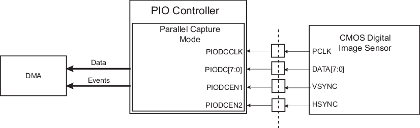
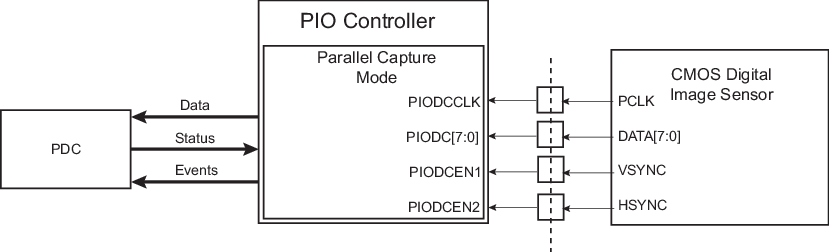
As soon as the Parallel Capture mode is enabled by writing a one to the PCEN bit in PIO_PCMR, the I/O lines connected to the sensor clock (PIODCCLK), the sensor data (PIODC[7:0]) and the sensor data enable signals (PIODCEN1 and PIODCEN2) are configured automatically as inputs. To know which I/O lines are associated with the sensor clock, the sensor data and the sensor data enable signals, refer to the I/O multiplexing table(s) in the section “Package and Pinout”.
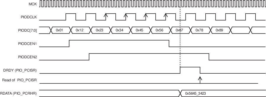
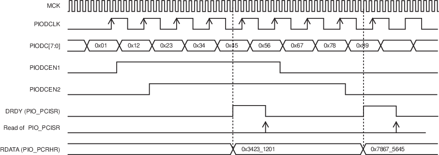
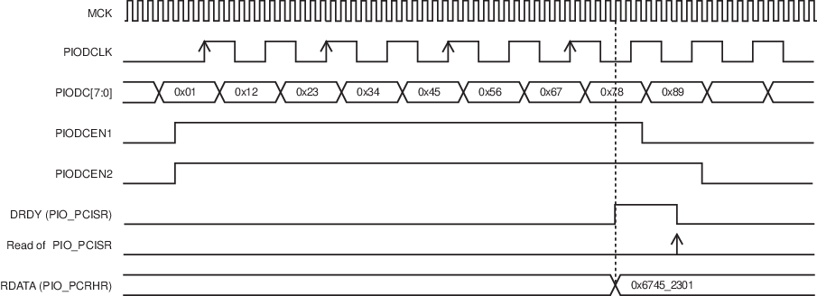
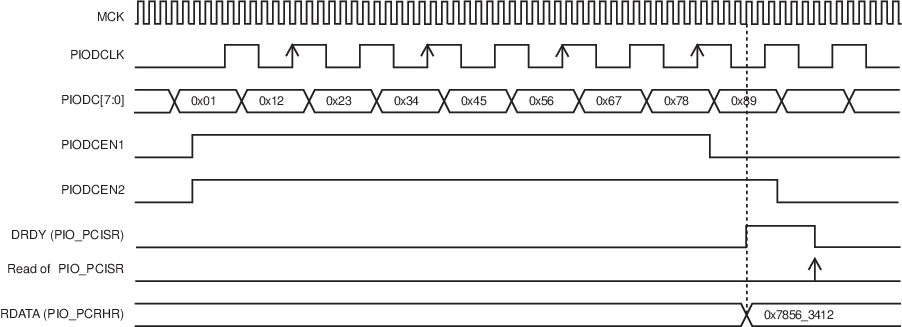
Once enabled, the Parallel Capture mode samples the data at rising edge of the sensor clock and resynchronizes it with the peripheral clock domain.
The size of the data which can be read in PIO_PCRHR can be programmed using the DSIZE field in PIO_PCMR. If this data size is larger than 8 bits, then the Parallel Capture mode samples several sensor data to form a concatenated data of size defined by DSIZE. Then this data is stored in PIO_PCRHR and the flag DRDY is set to one in PIO_PCISR.
The Parallel Capture mode can be associated with a reception channel of the DMA Controller. This performs reception transfer from Parallel Capture mode to a memory buffer without any intervention from the CPU.
The Parallel Capture mode can take into account the sensor data enable signals or not. If the bit ALWYS is set to zero in PIO_PCMR, the Parallel Capture mode samples the sensor data at the rising edge of the sensor clock only if both data enable signals are active (at one). If the bit ALWYS is set to one, the Parallel Capture mode samples the sensor data at the rising edge of the sensor clock whichever the data enable signals are.
The Parallel Capture mode can sample the sensor data only one time out of two. This is particularly useful when the user wants only to sample the luminance Y of a CMOS digital image sensor which outputs a YUV422 data stream. If the HALFS bit is set to zero in PIO_PCMR, the Parallel Capture mode samples the sensor data in the conditions described above. If the HALFS bit is set to one in PIO_PCMR, the Parallel Capture mode samples the sensor data in the conditions described above, but only one time out of two. Depending on the FRSTS bit in PIO_PCMR, the sensor can either sample the even or odd sensor data. If sensor data are numbered in the order that they are received with an index from zero to n, if FRSTS equals zero then only data with an even index are sampled. If FRSTS equals one, then only data with an odd index are sampled. If data is ready in PIO_PCRHR and it is not read before a new data is stored in PIO_PCRHR, then an overrun error occurs. The previous data is lost and the OVRE flag in PIO_PCISR is set to one. This flag is automatically reset when PIO_PCISR is read (reset after read).
The flags DRDY and OVRE can be a source of the PIO interrupt.