After filtering, the quadrature signals are analyzed to extract the rotation direction and edges of the two quadrature signals detected in order to be counted by TC logic downstream.
The direction status can be directly read at anytime in the TC_QISR. The polarity of the direction flag status depends on the configuration written in TC_BMR. INVA, INVB, INVIDX, SWAP modify the polarity of DIR flag.
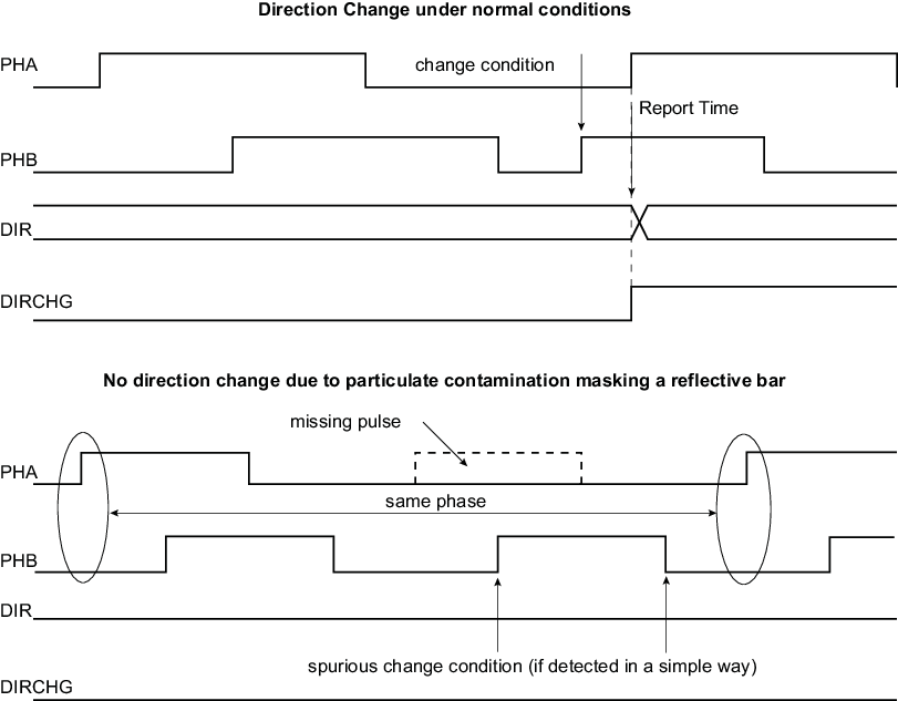
Any change in rotation direction is reported in the TC_QISR and can generate an interrupt.
The direction change condition is reported as soon as two consecutive edges on a phase signal have sampled the same value on the other phase signal and there is an edge on the other signal. The two consecutive edges of one phase signal sampling the same value on other phase signal is not sufficient to declare a direction change, as particulate contamination may mask one or more reflective bars on the optical or magnetic disk of the sensor. Refer to the following figure for waveforms.
The direction change detection is disabled when TC_BMR.QDTRANS is set. In this case, the DIR flag report must not be used.
A quadrature error is also reported by the QDEC via TC_QISR.QERR. This error is reported if the time difference between two edges on PHA, PHB is lower than a predefined value. This predefined value is configurable and corresponds to (TC_BMR.MAXFILT + 1) × tperipheral clock ns. After being filtered, there is no reason to have two edges closer than (TC_BMR.MAXFILT + 1) × tperipheral clock ns under normal mode of operation.
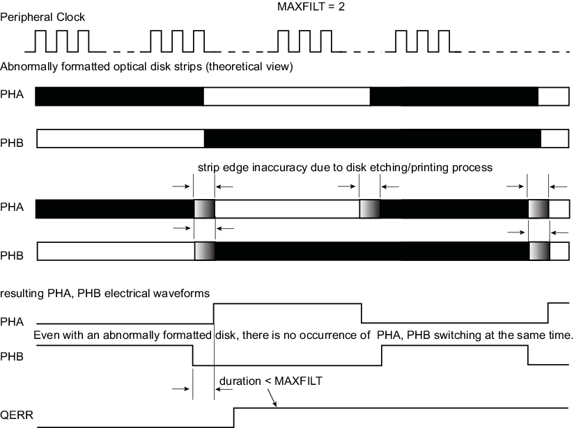
MAXFILT must be tuned according to several factors such as the peripheral clock frequency, type of rotary sensor and rotation speed to be achieved.