The PIO Controller can be programmed to generate an interrupt when it detects an edge or a level on an I/O line. The Input Edge/Level interrupt is controlled by writing the Interrupt Enable Register (PIO_IER) and the Interrupt Disable Register (PIO_IDR), which enable and disable the input change interrupt respectively by setting and clearing the corresponding bit in the Interrupt Mask Register (PIO_IMR). As input change detection is possible only by comparing two successive samplings of the input of the I/O line, the peripheral clock must be enabled. The Input Change interrupt is available regardless of the configuration of the I/O line, i.e., configured as an input only, controlled by the PIO Controller or assigned to a peripheral function.
By default, the interrupt can be generated at any time an edge is detected on the input.
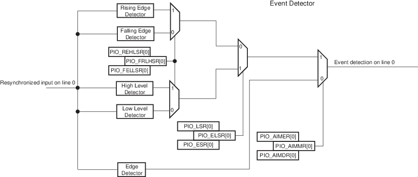
Some additional interrupt modes can be enabled/disabled by writing in the Additional Interrupt Modes Enable Register (PIO_AIMER) and Additional Interrupt Modes Disable Register (PIO_AIMDR). The current state of this selection can be read through the Additional Interrupt Modes Mask Register (PIO_AIMMR).
These additional modes are:
- Rising edge detection
- Falling edge detection
- Low-level detection
- High-level detection
In order to select an additional interrupt mode:
- The type of event detection (edge or level) must be selected by writing in the Edge Select Register (PIO_ESR) and Level Select Register (PIO_LSR) which select, respectively, the edge and level detection. The current status of this selection is accessible through the Edge/Level Status Register (PIO_ELSR).
- The polarity of the event detection (rising/falling edge or high/low-level) must be selected by writing in the Falling Edge/Low-Level Select Register (PIO_FELLSR) and Rising Edge/High-Level Select Register (PIO_REHLSR) which allow to select falling or rising edge (if edge is selected in PIO_ELSR) edge or high- or low-level detection (if level is selected in PIO_ELSR). The current status of this selection is accessible through the Fall/Rise - Low/High Status Register (PIO_FRLHSR).
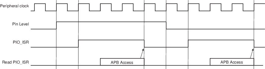
When an input edge or level is detected on an I/O line, the corresponding bit in the Interrupt Status Register (PIO_ISR) is set. If the corresponding bit in PIO_IMR is set, the PIO Controller interrupt line is asserted.The interrupt signals of the 32 channels are ORed-wired together to generate a single interrupt signal to the interrupt controller.
When the software reads PIO_ISR, all the interrupts are automatically cleared. This signifies that all the interrupts that are pending when PIO_ISR is read must be handled. When an Interrupt is enabled on a “level”, the interrupt is generated as long as the interrupt source is not cleared, even if some read accesses in PIO_ISR are performed.
Example of interrupt generation on following lines:
- Rising edge on PIO line 0
- Falling edge on PIO line 1
- Rising edge on PIO line 2
- Low-level on PIO line 3
- High-level on PIO line 4
- High-level on PIO line 5
- Falling edge on PIO line 6
- Rising edge on PIO line 7
- Any edge on the other lines
The following table provides the required configuration for this example.
| Configuration | Description |
|---|---|
| Interrupt Mode | All the interrupt sources are enabled by writing 32’hFFFF_FFFF in PIO_IER. Then the additional Interrupt mode is enabled for lines 0 to 7 by writing 32’h0000_00FF in PIO_AIMER. |
| Edge or Level Detection | Lines 3, 4 and 5 are configured in level detection by writing 32’h0000_0038 in PIO_LSR. The other lines are configured in edge detection by default, if they have not been previously configured. Otherwise, lines 0, 1, 2, 6 and 7 must be configured in edge detection by writing 32’h0000_00C7 in PIO_ESR. |
| Falling/Rising Edge or Low/High-Level Detection | Lines 0, 2, 4, 5 and 7 are configured in rising edge or high-level detection by writing 32’h0000_00B5 in PIO_REHLSR. The other lines are configured in falling edge or low-level detection by default if they have not been previously configured. Otherwise, lines 1, 3 and 6 must be configured in falling edge/low-level detection by writing 32’h0000_004A in PIO_FELLSR. |