The 3-pin MediaLB data structure consists of a ChannelAddress, a Tx command (Command), an Rx response (RxStatus), and four data bytes (Data).
A MediaLB data structure flow is:
- The MediaLB Controller places a ChannelAddress on the MLBS line. This addresses two or more MediaLB Devices. One acts as a Tx MediaLB Device and the other or others act as Rx MediaLB Devices.
- After a fixed delay of 4 bytes (one quadlet or physical channel), the addressed Tx MediaLB Device responds by shifting out a command byte (Command) onto the MLBS line, coincident with the start of 4 bytes of data onto the MLBD line.
- The Rx MediaLB Device responds in the same physical channel by
shifting out its status response (RxStatus) onto the MLBS line after the Tx Device’s
Command. The RxStatus reports the status of the receiving Device to the sender. For
asynchronous, control and isochronous (non-broadcast) transmissions, the data sent is
accepted if the receiver presents a status response of ReceiverReady or rejected if the
receiver presents a status response of ReceiverBusy. For synchronous and isochronous
(broadcast) transmissions, the receiving Device must not drive any RxStatus, thereby
defaulting to ReceiverReady. Synchronous (and some isochronous) data is sent in a
broadcast fashion and supports multiple receiving Devices.Figure 1. 3-pin MediaLB Data Structure
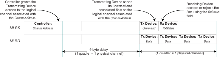
During normal operation, the MediaLB Controller initiates a transfer by sending out the ChannelAddress on the MLBS line, and then stops driving (high-impedance) the MLBS line. When a MediaLB Device recognizes the ChannelAddress as related to one of its channels, the Tx Device will generate the Command on the MLBS line and place the data on the MLBD line. The Rx Device will generate the RxStatus on the MLBS line, after the Command. Both Command and RxStatus are output in the second quadlet after the matching ChannelAddress occurred. If the Rx Device reports a status response of ReceiverBusy, then the Tx Device must retransmit the Command and Data in the next physical channel assigned to that same ChannelAddress (next quadlet in the logical channel). If the Tx Device transmits the NoData command, the Rx Device ignores the data on the MLBD line.
This results in the following scheme:
Controller: ChannelAddress → Tx Device: Command → Rx Device: RxStatus
Since for synchronous data transmission (SyncData) the status response must always be ReceiverReady (bus default when signal not driven), synchronous data supports broadcast transmission to multiple Rx Devices.
After the Tx Device outputs Command, it must stop driving the MLBS line to allow the Rx Device to output RxStatus. At the end of the physical channel, the Tx Device must also stop driving the MLBD line unless the ChannelAddress for the next physical channel is also assigned to it. Likewise, after the Rx Device outputs RxStatus, it must stop driving the MLBS line to allow the Controller to output another ChannelAddress.
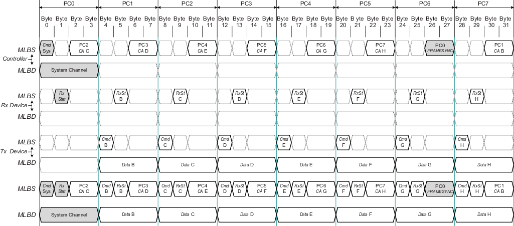
Figure 2 illustrates which Device is driving the MediaLB signal and data lines, using the 256Fs speed as an example. Depending on the number of physical channels that are grouped into logical channels, fewer unique ChannelAddresses may be seen in the frame. In Figure 2, each logical channel is one quadlet (one physical channel), mapping to seven ChannelAddresses (B through H). If one logical channel consisted of two quadlets and another consisted of three quadlets, then only four unique ChannelAddresses would be seen on MediaLB (B through E).
For MediaLB synchronization purposes, ChannelAddress 0x01FE is defined as the FRAMESYNC pattern. The MediaLB Controller generates this pattern once per MOST Network frame on the MLBS line. The MediaLB link layer is designed to ensure that this bit pattern is unique on the bus.
All MediaLB Devices must synchronize their byte boundary and their physical channel boundary upon receiving the FRAMESYNC pattern. The end of the FRAMESYNC pattern also indicates that four bytes later is the start of the MediaLB frame (PC0), and the System Channel. The actual number of physical channels supported is determined by the MediaLB clock speed. the following table illustrates the number of available quadlets and physical channels per frame for 3-pin MediaLB speed modes.
| MediaLB Speed | Physical Channels per Frame | Available Physical Channels per Frame (see Note) |
|---|---|---|
| 256×Fs | 8 | 7 (PC1–PC7) |
| 512×Fs | 16 | 15 (PC1–PC15) |
The MLBS and MLBD physical channel associated with the FRAMESYNC ChannelAddress (PC0), is defined as the System Channel and can be used by the Controller to broadcast system control and status information to all Devices. Examples of System commands are MLBReset and MLBScan. Status examples include MOSTLock and MOSTUnlock which indicate the status of the MOST Network to MediaLB Devices.
MediaLB supports both static physical channel assignments or dynamic implementations. As an example of a static implementation, the Controller can automatically open a pair of logical channels at power-up. Through these channels, the rest of the MediaLB bandwidth can be configured by a MediaLB Device (generally the EHC). For a dynamic implementation, the EHC can request the Controller to scan for specific DeviceAddresses and then configure the Devices found (see the MLBScan System command).