Optional input glitch and debouncing filters are independently programmable on each I/O line.
The glitch filter can filter a glitch with a duration of less than 1/2 peripheral clock and the debouncing filter can filter a pulse of less than 1/2 period of a programmable divided slow clock.
The selection between glitch filtering or debounce filtering is done by writing in the PIO Input Filter Slow Clock Disable Register (PIO_IFSCDR) and the PIO Input Filter Slow Clock Enable Register (PIO_IFSCER). Writing PIO_IFSCDR and PIO_IFSCER, respectively, sets and clears bits in the Input Filter Slow Clock Status Register (PIO_IFSCSR).
The current selection status can be checked by reading the PIO_IFSCSR.
- If PIO_IFSCSR[i] = 0: The glitch filter can filter a glitch with a duration of less than 1/2 master clock period.
- If PIO_IFSCSR[i] = 1: The debouncing filter can filter a pulse with a duration of less than 1/2 programmable divided slow clock period.
For the debouncing filter, the period of the divided slow clock is defined by writing in the DIV field of the Slow Clock Divider Debouncing Register (PIO_SCDR):
tdiv_slck = ((DIV + 1) × 2) × tslck
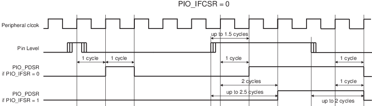
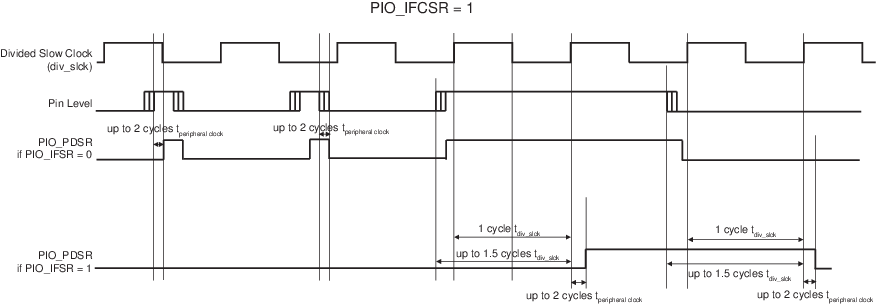
When the glitch or debouncing filter is enabled, a glitch or pulse with a duration of less than 1/2 selected clock cycle (selected clock represents peripheral clock or divided slow clock depending on PIO_IFSCDR and PIO_IFSCER programming) is automatically rejected, while a pulse with a duration of one selected clock (peripheral clock or divided slow clock) cycle or more is accepted. For pulse durations between 1/2 selected clock cycle and one selected clock cycle, the pulse may or may not be taken into account, depending on the precise timing of its occurrence. Thus for a pulse to be visible, it must exceed one selected clock cycle, whereas for a glitch to be reliably filtered out, its duration must not exceed 1/2 selected clock cycle.
The filters also introduce some latencies, illustrated in the following two figures.
The glitch filters are controlled by the Input Filter Enable Register (PIO_IFER), the Input Filter Disable Register (PIO_IFDR) and the Input Filter Status Register (PIO_IFSR). Writing PIO_IFER and PIO_IFDR respectively sets and clears bits in PIO_IFSR. This last register enables the glitch filter on the I/O lines.
When the glitch and/or debouncing filter is enabled, it does not modify the behavior of the inputs on the peripherals. It acts only on the value read in PIO_PDSR and on the input change interrupt detection. The glitch and debouncing filters require that the peripheral clock is enabled.