The Routing Fabric (RF) block manages the flow of data between the MediaLB Port and the HBI Port. Bus multiplexers and a bus arbiter are implemented in the RF block for accessing the channel table RAM (CTR) and data buffer RAM (DBR).
Each DMA controller in the routing fabric uses Channel Descriptors (stored in the CTR) to manage access to dynamic buffers in the DBR.
Data Buffer RAM
The MLB has an external data buffer RAM (DBR) that is 8-bit x 16k entries deep. The DBR provides dynamic circular buffering between the transmit and receive devices.
The size and location of each data buffer is defined by software in the channel descriptor table (CDT), which is located in the CTR.
Receive devices retain the write address pointer to the associated circular data buffer in the DBR, while transmit devices retain the read address pointer. The DMA controllers in the routing fabric are responsible for ensuring that the circular buffers do not overflow or underflow. Each channel type (e.g., synchronous, isochronous, asynchronous and control) has Full and Empty detection.
- Synchronous Channels
For synchronous channels, two mechanisms prevent overflow and underflow of the data buffer:
- Hardware aligns the read pointer (RPTR) to the write pointer (WPTR) to ensure an offset of two sub-buffers.
- RPTR and WPTR are periodically synchronized to the start of the next sub-buffer (e.g. following a FRAMESYNC).
- Isochronous Channels
For isochronous channels, hardware does not read from an empty data buffer or write to a full data buffer. The conditions used by hardware for detection include:
Data buffer Empty condition: (RPTR = WPTR) AND (BF = 0), and
Data buffer Full condition: (WPTR = RPTR) AND (BF = 1).
- Asynchronous and Control Channels
For asynchronous and control channels, hardware does not read from an empty data buffer or write to a full data buffer. Hardware evaluates the DMA pointers (RPTR, WPTR) and packet count (RPC, WPC) to detect the data buffer condition, where:
- Data buffer Empty condition: (RPTR = WPTR) AND (RPC = WPC), and
- Data buffer Full condition: ((WPTR = RPTR) AND (WPC != RPC)) OR (WPC = (RPC - 1)).
Channel Table RAM
The MLB has an external Channel Table RAM (CTR) that is 128-bit x 144-entry. The CTR allows system software to dynamically configure channel routing and allocate data buffers in the DBR.
The CTR is logically divided into three sub-tables:
- Channel Descriptor Table (CDT)
- AHB Descriptor Table (ADT)
- Channel Allocation Table (CAT)
Address Mapping
| Label | Address | Bits 127…96 | Bits 95…64 | Bits 63…32 | Bits 31…0 | ||||
|---|---|---|---|---|---|---|---|---|---|
| Channel Descriptor Table (CDT): | |||||||||
| CDT | 0x00 | CDT0[127:0], CL = 0 | |||||||
| 0x01 | CDT1[127:0], CL = 1 | ||||||||
| 0x02 | CDT2[127:0], CL = 2 | ||||||||
| ... | ... | ||||||||
| 0x3D | CDT61[127:0], CL = 61 | ||||||||
| 0x3E | CDT62[127:0], CL = 62 | ||||||||
| 0x3F | CDT63[127:0], CL = 63 | ||||||||
| AHB Descriptor Table (ADT): | |||||||||
| ADT(1) | 0x40 | ADT0[127:0] | |||||||
| 0x41 | ADT1[127:0] | ||||||||
| 0x42 | ADT2[127:0] | ||||||||
| ... | ... | ||||||||
| 0x7D | ADT61[127:0] | ||||||||
| 0x7E | ADT62[127:0] | ||||||||
| 0x7F | ADT63[127:0] | ||||||||
| Channel Allocation Table (CAT): | |||||||||
| CAT for MediaLB | 0x80 | CAT7 | CAT6 | CAT5 | CAT4 | CAT3 | CAT2 | CAT1 | CAT0 |
| ... | ... | ... | ... | ... | ... | ... | ... | ... | |
| 0x87 | CAT63 | CAT62 | CAT61 | CAT60 | CAT59 | CAT58 | CAT57 | CAT56 | |
| CAT for HBI(1) | 0x88 | CAT71 | CAT70 | CAT69 | CAT68 | CAT67 | CAT66 | CAT65 | CAT64 |
| ... | ... | ... | ... | ... | ... | ... | ... | ... | |
| 0x8F | CAT127 | CAT126 | CAT125 | CAT124 | CAT123 | CAT122 | CAT121 | CAT120 | |
Note: 1. A fixed relationship exists between ADT entries and HBI CAT entries. When using HBI channel 0 (CAT64) one should program ADT0. When using HBI channel 1 (CAT65) one should program ADT1, and so on.
Channel Allocation Table
The Channel Allocation Table (CAT) is comprised of 16 CTR entries (addresses 0x80–0x8F), as shown in Table 1-12. Each 16-bit CAT entry represents a logical connection to or from a transmit/receive device (e.g. MediaLB or HBI channel). All entries are indexed according to a fixed physical address assigned to every Rx/Tx channel (as shown in the following table). The value stored in a CAT entry includes a 6-bit Connection Label, which provides a pointer to the CDT. To complete a logical channel and form a routing connection, system software must assign the same Connection Label to both the Rx and Tx channels.
| Peripheral | Tx Channels | Rx Channels | CAT Start Index | CAT End Index | Entries |
|---|---|---|---|---|---|
| MediaLB | 0 to 64 | 64 - Tx Channels | 0 | 63 | 64 |
| HBI | 0 to 64 | 64 - Tx Channels | 64 | 127 | 64 |
The format of a full CAT entry is shown in Table 3, with field descriptions described in Table 4. All reserved bits of a CAT entry field should be written as zero.
| Channel Type | 15 | 14 | 13 | 12 | 11 | 10 | 9 | 8 | 7 | 6 | 5 | 4 | 3 | 2 | 1 | 0 |
|---|---|---|---|---|---|---|---|---|---|---|---|---|---|---|---|---|
| Isochronous | rsvd | FCE | rsvd | RNW | CE | CT[2:0] = 3 | rsvd | CL[5:0] | ||||||||
| Asynchronous | rsvd | MT | RNW | CE | CT[2:0] = 2 | rsvd | CL[5:0] | |||||||||
| Control | rsvd | MT | RNW | CE | CT[2:0] = 1 | rsvd | CL[5:0] | |||||||||
| Synchronous | rsvd | MFE | MT | RNW | CE | CT[2:0] = 0 | rsvd | CL[5:0] | ||||||||
| Field | Description |
|---|---|
| CL[5:0] | Connection Label (offset into CDT) |
| CT[2:0] | Channel Type (Others):
111 = Reserved
110 = Reserved
101 = Reserved
100 = Reserved 011 = Isochronous 010 = Asynchronous 001 = Control 000 = Synchronous |
| CE | Channel Enable: 1 = Enabled 0 = Disabled |
| RNW | Read Not Write: 1 = Read 0 = Write |
| MT | Mute Enable (1): 1 = Enabled 0 = Disabled |
| FCE | Flow Control Enable (2): 1 = Enabled 0 = Disabled |
| MFE | Multi-Frame per Sub-buffer Enable(3): 1 = Enabled 0 = Disabled |
| rsvd | Reserved. Software writes a zero to all reserved bits when the entry is initialized. The reserved bits are Read-only after initialization. |
Notes: 1. When set for synchronous channels, the MT bit forces Rx channels to write zeros into the channel data buffer, and Tx channels to output zeros on the physical interface. When set for asynchronous and control channels, the MT bit causes DMA to halt at a packet boundary. Not valid for isochronous channels.
2. The FCE bit is used by MediaLB isochronous Rx channels only.
3. The MFE bit is used by MediaLB synchronous channels only.
Channel Setup
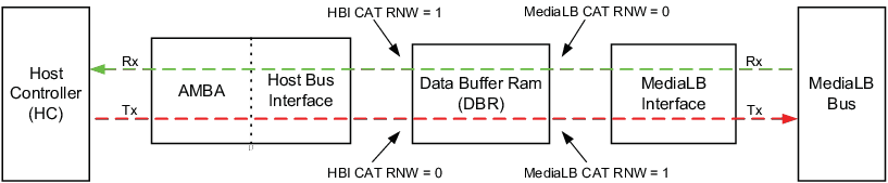
Data direction in the MLB is in reference to the DBR. Therefore, the data direction of CAT entries corresponding to the same channel is reversed for the HBI CAT and the MediaLB CAT.
For a Tx channel (from the HC to the MediaLB interface):
- HBI CAT entry: RNW = 0 (write)
- MediaLB CAT entry: RNW = 1 (read)
Conversely, for a Rx channel (data from MediaLB to HC):
- HBI CAT entry: RNW = 1 (read)
- MediaLB CAT entry: RNW = 0 (write)
The figure below illustrates the directional relationship in the MLB.
Channel Descriptor Table
The Channel Descriptor Table (CDT) is comprised of 64 CTR entries (addresses 0x00–0x3F), as shown in Table 1.
Each 128-bit CDT entry (also referred to as a Channel Descriptor) is referenced by a Connection Label and contains information about a data buffer in the DBR (e.g., buffer size, address pointers).
The format of each CDT entry (also referred to as a Channel Descriptor) depends on the channel type (e.g. synchronous, isochronous, asynchronous, or control).
Note: All reserved Channel Descriptor bits must be written to ‘0’ by software when initialized.
Synchronous Channel Operation
The MLB provides two modes of operation (Standard and Multi-Frame per Sub- buffer) to provide flexibility for implementing synchronous channels.
Channels set up for Standard mode require less buffer space, but have higher interrupt rates and more stringent latency requirements. For channels configured for Standard mode, the Host Controller must transfer one full frame of streaming data in/out of each streaming channel's data buffer for each frame period.
Channels set up for Multi-Frame per Sub-buffer mode require more buffer space, but have lower interrupt rates and less stringent latency requirements. For channels configured for Multi-Frame per Sub-buffer mode, the Host Controller must transfer N full frames of streaming data in/out of each streaming channel's data buffer for each frame period.
To set up a channel in Multi-Frame per Sub-buffer mode:
- Program MLB_MLBC0.FCNT[2:0] to select the number of frames per sub-buffer
- Program the CAT to enable multi-frame sub-buffering (MFE = 1) for each particular channel
- Set the buffer depth in the CDT: BD = 4 × m × bpf - 1, where m = frames per sub- buffer, bpf = bytes per frame
- Repeat for additional synchronous channels
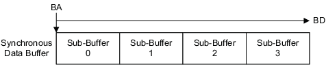
A sample synchronous data buffer is shown in the following figure. Each data buffer contains four sub-buffers and each sub-buffer contains space for 1 to 64 frames of data, determined by MLB_MLBC0.FCNT[2:0].
Synchronous Channel Descriptors
The format and field definitions for a synchronous CDT entry are shown in Table 5 and Table 5, respectively.
| Bit Offset | 15 | 14 | 13 | 12 | 11 | 10 | 9 | 8 | 7 | 6 | 5 | 4 | 3 | 2 | 1 | 0 |
|---|---|---|---|---|---|---|---|---|---|---|---|---|---|---|---|---|
| 0 | WSBC | Reserved | ||||||||||||||
| 16 | RSBC | Reserved | ||||||||||||||
| 32 | Reserved | |||||||||||||||
| 48 | Reserved | |||||||||||||||
| 64 | WSTS[3:0] | WPTR[11:0] | ||||||||||||||
| 80 | RSTS[3:0] | RPTR[11:0] | ||||||||||||||
| 96 | Reserved | BD[11:0] | ||||||||||||||
| 112 | Reserved | BA[13:0] | ||||||||||||||
| Field | Description | Details | Accessibility |
|---|---|---|---|
| BA | Buffer Base Address | - BA can start at any byte in the 16k DBR | r,w |
| BD | Buffer Depth | - BD = size of buffer in bytes - 1 - Buffer end address = BA + BD - BD = 4 x m x bpf - 1, where: m = frames per sub-buffer (for MFE = 0, m = 1) bpf = bytes per frame. |
r,w |
| RPTR | Read Pointer | - Software initializes to zero, hardware updates - Counts the read address offset within a buffer - DMA read address = BA + RPTR |
r,w,u(1) |
| WPTR | Write Pointer | - Software initializes to zero, hardware updates - Counts the write address offset within a buffer - DMA write address = BA + WPTR |
r,w,u (1) |
| RSBC | Read Sub-buffer Counter | - Software initializes to zero, hardware updates - Counts the read sub-buffer offset - DMA uses for pointer management |
r,w,u (1) |
| WSBC | Write Sub-buffer Counter | - Software initializes to zero, hardware updates - Counts the write sub-buffer offset - DMA uses for pointer management |
r,w,u (1) |
| RSTS | Read Status | - Software initializes to zero, hardware updates - RSTS states:(2) xxx0 = normal operation (no mute) xxx1 = normal operation (mute) xx0x = idle |
r,w,u (1) |
| WSTS | Write Status | - Software initializes to zero, hardware updates - WSTS states:(2) xxx0 = normal operation (no mute) xxx1 = normal operation (mute) xx0x = idle 1xxx = command protocol error |
r,w,u (1) |
| Reserved | Reserved | - Software writes a zero to all reserved bits when the entry is initialized. The reserved bits are Read-only after initialization. | r,w,u (1) |
Notes: 1. “u” means “Updated periodically by hardware”.
2. Only valid for DMA pointers associated with the MediaLB block (Not valid for HBI block related pointers).
Isochronous Channel Descriptors
The format and field definitions for an isochronous CDT entry are shown in Table 7 and Table 8, respectively.
| Bit Offset | 15 | 14 | 13 | 12 | 11 | 10 | 9 | 8 | 7 | 6 | 5 | 4 | 3 | 2 | 1 | 0 |
|---|---|---|---|---|---|---|---|---|---|---|---|---|---|---|---|---|
| 0 | Reserved | |||||||||||||||
| 16 | Reserved | |||||||||||||||
| 32 | Reserved | BS[8:0] | ||||||||||||||
| 48 | Reserved | |||||||||||||||
| 64 | WSTS[2:0] | WPTR[12:0] | ||||||||||||||
| 80 | RSTS[2:0] | RPTR[12:0] | ||||||||||||||
| 96 | Reserved | BD[12:0] | ||||||||||||||
| 112 | BF | rsvd | BA[13:0] | |||||||||||||
| Field | Description | Details | Accessibility |
|---|---|---|---|
| BA | Buffer Base Address | - BA can start at any byte in the 16k DBR | r,w |
| BD | Buffer Depth | - BD = size of buffer in bytes - 1 - Buffer end address = BA + BD - Isochronous buffers must be large enough to hold at least 3 blocks (packets) of data - Buffer depth must be a integer multiple of blocks |
r,w |
| BF | Buffer Full | - Software initializes to zero, hardware updates - DMA write hardware sets BF when the buffer is full - DMA read hardware clears BF when the buffer is empty - BF is valid only when the buffer is full or empty, otherwise ignore |
r,w,u (1) |
| BS | Block Size | - BS defines when to begin the DMA to the data buffer - BS = buffer block size in bytes - 1 - For Rx channels, the DMA writes start when the number of empty bytes (SPACE) in the data buffer ≥ the block size - For Tx channels, the DMA reads start when the number of valid bytes (VALID) in the data buffer ≥ the block size |
r,w,u (1) |
| RPTR | Read Pointer | - Software initializes to zero, hardware updates - Counts the read address offset within a buffer - DMA read address = BA + RPTR |
r,w,u (1) |
| WPTR | Write Pointer | - Software initializes to zero, hardware updates - Counts the write address offset within a buffer - DMA write address = BA + WPTR |
r,w,u (1) |
| RSTS | Read Status | - Software initializes to zero, hardware updates - RSTS states:(2) xx1 = active xx0 = idle |
r,w,u (1) |
| WSTS | Write Status | - Software initializes to zero, hardware updates - WSTS states:(2) xx1 = active xx0 = idle x1x = command protocol error 1xx = buffer overflow (FCE = 0 only) |
r,w,u (1) |
| Reserved | Reserved | - Software writes a zero to all Reserved bits when the entry is initialized. The Reserved bits are Read-only after initialization. | r,w,u (1) |
Notes: 1. “u” means “Updated periodically by hardware”.
2. Only valid for DMA pointers associated with the MediaLB block (Not valid for HBI block related pointers).
Asynchronous and Control Channel Descriptors
The format and field definitions for asynchronous and control CDT entries are shown in Table 9 and Table 10, respectively.
| Bit Offset | 15 | 14 | 13 | 12 | 11 | 10 | 9 | 8 | 7 | 6 | 5 | 4 | 3 | 2 | 1 | 0 |
|---|---|---|---|---|---|---|---|---|---|---|---|---|---|---|---|---|
| 0 | WPC[4:0] | Reserved | ||||||||||||||
| 16 | RPC[4:0] | Reserved | ||||||||||||||
| 32 | rsvd | WPC[7:5] | Reserved | |||||||||||||
| 48 | rsvd | RPC[7:5] | Reserved | |||||||||||||
| 64 | WSTS[3:0] | WPTR[11:0] | ||||||||||||||
| 80 | RSTS[3:0] | RPTR[11:0] | ||||||||||||||
| 96 | RSTS[4] | WSTS[4] | rsvd | BD[11:0] | ||||||||||||
| 112 | Reserved | BA[13:0] | ||||||||||||||
| Field | Description | Details | Accessibility |
|---|---|---|---|
| BA | Buffer Base Address | - BA can start at any byte in the 16k DBR | r,w |
| BD | Buffer Depth | - BD = size of buffer in bytes - 1 - Buffer end address = BA + BD - BD ≥ max packet length - 1 |
r,w |
| RPC | Read Packet Count | - Software initializes to zero, hardware updates - Used in conjunction with WPC, RPTR and WPTR to determine if the buffer is empty or full |
r,w,u (1) |
| WPC | Write Packet Count | - Software initializes to zero, hardware updates - Used in conjunction with RPC, RPTR and WPTR to determine if the buffer is empty or full |
r,w,u (1) |
| RPTR | Read Pointer | - Software initializes to zero, hardware updates - Counts the read address offset within a buffer - DMA read address = BA + RPTR |
r,w,u (1) |
| WPTR | Write Pointer | - Software initializes to zero, hardware updates - Counts the write address offset within a buffer - DMA read address = BA + WPTR |
r,w,u (1) |
| RSTS | Read Status | - Software initializes to zero, hardware updates - Status states:(2) x0x00 = idle xx1xx = ReceiverProtocolError response received from Rx Device 1xxxx = ReceiverBreak command received from Rx Device |
r,w,u (1) |
| WSTS | Write Status | - Software initializes to zero, hardware updates - Status states:(2) x0x00 = idle xx1xx = command protocol error detected 1xxxx = AsyncBreak/ControlBreak command received from Tx Device |
r,w,u (1) |
| Reserved | Reserved | Software writes a zero to all reserved bits when the entry is initialized. The reserved bits are Read-only after initialization. | r,w,u (1) |
Notes: 1. “u” means “Updated periodically by hardware”.
2. Only valid for DMA pointers associated with the MediaLB block (not valid for HBI block related pointers).